VFD for Centrifugal Pumps
Centrifugal pumps are generally sized to operate at or near the best efficiency point at maximum flow. The maximum flow requirements, however, frequently occur for a very short period during the operating cycle with the result that some method of flow control is required. The traditional method to flow control has used valves, which increase system pressure, inherently waste energy, and generally cause the centrifugal pump to operate at reduced efficiencies.
VFDs (Variable Frequency Drives) can achieve reduced flow by providing variable speed pump operation. This results in reduced system pressure and operation near the pump's Best Efficiency Point. In addition, maintenance costs might be reduced. This article will discuss the energy savings potential of variable frequency drives followed by a brief description of the operation and relative benefits of VFDs.
Centrifugal Pump Applications and Energy Savings
Centrifugal pumps are used on many industrial and commercial applications. Many of these pumps are operated at fixed speeds, but could provide energy savings through variable speed operation. Reviewing the affinity laws for centrifugal pumps and a typical operating cycle for a centrifugal application will show this.
Figure 1 shows the physical laws of centrifugal pumping applications. The flow is directly proportional to speed; pressure is proportional to the square of the speed; and power is proportional to the cube of the speed. These relationships can also be expressed numerically as shown in Table 1. Theoretically, it would be possible to operate at 50% flow with only 13% of the power required at 100% flow. Since the power requirements decrease much faster than the reduction in flow, the potential exists for significant energy reduction at reduced flows.

Fig. 1 Centrifugal Pumps Affinity Laws
Table 1
These characteristics are important when one considers a typical duty cycle for a centrifugal pump application. A typical operating cycle might be represented by the bar chart shown in figure 2. Centrifugal pumps are generally sized to handle the peak flow requirements, which typically occur for very short periods of time. Consequently, the equipment would be operated at reduced flows most of the time. For this example, the system would be operated below 70% flow over 94% of the time. Thus, this sort of duty cycle could provide energy savings by variable speed operation of the centrifugal pump.
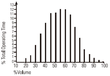
Fig. 2 Typical Centrifugal Pump Duty Cycle
Centrifugal Pump Basics
An understanding of the basic operating characteristics of centrifugal pumps is necessary to apply variable frequency drives to this particular application.
Figure 3 shows a centrifugal pump curve describing the head (or pressure) versus flow characteristics of a typical centrifugal pump. This curve shows that the centrifugal pump will produce limited flow if applied to a piping system in which a large pressure differential is required across the pump to lift the liquid and overcome resistance to flow (as at point A). Higher flow rates can be achieved as the required pressure differential is reduced (as at point B).
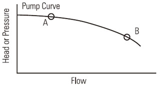
Fig. 3 Typical Centrifugal Pump Curve
To determine where along this curve the centrifugal pump will operate in a given application requires the additional information provided by the system curve. This curve, shown in figure 4, represents the characteristics of the piping system to which the centrifugal pump is applied. The head required at zero flow is called the static head or lift.
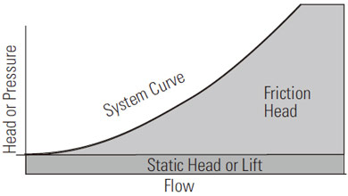
Fig. 4 System Curve
This shows how many feet of elevation that the centrifugal pump must lift the fluid regardless of the flow rate. Another way to describe static head is to think of it as the amount of work needed to overcome the effects of gravity.
The other component of head is called the friction head and increases with increasing flow. Friction head is a measure of the resistance to flow (back pressure) provided by the pipe and its associated valves, elbows, and other system elements.
The intersection of the centrifugal pump and system curves shows the natural operating point for the system without flow control, as shown in figure 5. This intersection would generally be chosen to ensure that the centrifugal pump is operated at or near its best efficiency point.
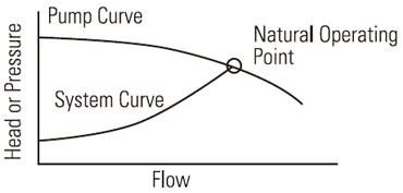
Fig. 5 Combined Curves
Figure 6 shows a typical centrifugal pump and efficiency curve for operation at a fixed speed. It can be seen that for fixed speed operation, the efficiency varies as flow is adjusted. For variable speed operation however, the affinity laws predict that the centrifugal pump curve will shift downwards for reduced speed and the efficiency curve will shift to the left in such a way that efficiency will remain constant relative to points on the pump curve for reduced flows.
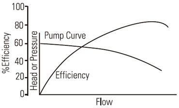
Fig. 6 Fixed Speed Pump Efficiency
Flow Control Techniques
Historically, fixed speed AC motors have driven centrifugal pumps and reduced flow has been achieved by using control valves as shown in figure 7. Closing the valve reduces the flow by increasing the friction in the system. The modified system curve and the new operating point can be represented as shown in figure 8. Note that the desired reduction in flow has been achieved, but at the expense of increased system pressure relative to 100% flow.
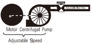
Fig. 7 Valve Control (An alternative approach to valve control is shown in figure 9.)
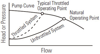
Fig. 8 Throttle System
Reducing the centrifugal pump speed causes the pump curve to shift downwards as shown in figure 9. Since the operating point is still determined by the intersection of the reduced speed pump curve and the system curve, it is possible to achieve the same reduced flow as achieved with a valve, but at significantly less pressure.
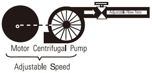
Fig. 9 Variable Speed Control
In addition to energy savings by VFD, which are discussed in detail later, operation at reduced pressures can result in longer pump seal life, reduced impeller wear, and less system vibration and noise. These benefits could provide additional savings over potential energy savings by variable frequency drive.
Energy Savings by Variable Frequency Drives
The centrifugal pump output power, or hydraulic power, can be expressed as:
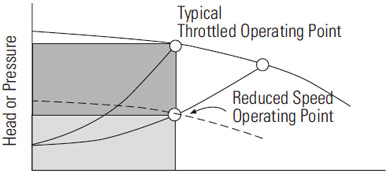
Fig. 10 Variable Speed Operation
The valve control rectangle includes both the dark and light shaded areas. Speed control uses only the lighter shaded portion of horsepower. Therefore, the potential energy saving available at this particular flow point is represented by the darker rectangle. This situation results in a substantial reduction in output power required through the use of variable frequency drive control rather than valve control (see differences between VFD and valve control). Relating this reduction in required output power to input power, which is the basis for the user's power bill, requires consideration of the efficiency of the centrifugal pump and flow control elements.
Efficiency can be expressed as:
Table 2. Energy Cost Comparison
(1) Typical 100 HP application. Flow control, when exercised, equals 70% of full flow. 4000 hours operation per year and $.07/KWH assumed.
(2) Slip control refers to fluid and magnetic couplings, often referred to as hydraulic or eddy current couplings. Wound rotor motors are also slip devices.
Thus, the first step toward realizing energy savings on centrifugal pumping applications is the decision to use VFD for pumps. The second step is to use the most efficient VFD that meets the application requirements.
VFD energy losses can vary substantially between VFD types, Solid-state drives have much lower losses than slip devices and closely approximate ideal, 100% efficient operating characteristics as shown in figure 11.
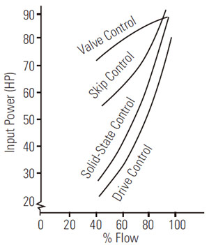
Fig. 11 Input Power Comparison
Efficiency Comparisons
Centrifugal pump efficiencies at various operating points are readily available from the pump manufacturer in the form of an efficiency map superimposed over the centrifugal pump curves for various impeller sizes as shown in figure 12.
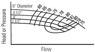
Fig. 12 Efficiencies for Various Impellers
The state-of-the-art has progressed dramatically in electronics in recent years. Advances in logic have produced large scale integrated and microprocessor devices that will continue to increase the capability of VFDs. Improvements in thyristors have resulted in decreased size while the development of IGBTs have expanded capabilities and size ranges. VFDs are expected to continue decreasing in cost and increasing in performance in the years to come. Besides longer-term energy savings, the initial cost differential between installing a VFD / motor package as compared to an AC starter/motor package is continually diminishing.
Dramatic increases in energy costs in recent years have made variable speed flow control through the use of VFDs economical in many instances. Large users of centrifugal pumping equipment would be wise to begin gaining experience with these VFDs now.
Conclusion
The most important choice to be made in choosing the VFDs is the decision to select a non-slip, solid-state VFD. Any such VFD can offer dramatic energy savings by efficiently matching the energy consumed to the hydraulic load requirements at any given moment.
VFDs (Variable Frequency Drives) can achieve reduced flow by providing variable speed pump operation. This results in reduced system pressure and operation near the pump's Best Efficiency Point. In addition, maintenance costs might be reduced. This article will discuss the energy savings potential of variable frequency drives followed by a brief description of the operation and relative benefits of VFDs.
Centrifugal Pump Applications and Energy Savings
Centrifugal pumps are used on many industrial and commercial applications. Many of these pumps are operated at fixed speeds, but could provide energy savings through variable speed operation. Reviewing the affinity laws for centrifugal pumps and a typical operating cycle for a centrifugal application will show this.
Figure 1 shows the physical laws of centrifugal pumping applications. The flow is directly proportional to speed; pressure is proportional to the square of the speed; and power is proportional to the cube of the speed. These relationships can also be expressed numerically as shown in Table 1. Theoretically, it would be possible to operate at 50% flow with only 13% of the power required at 100% flow. Since the power requirements decrease much faster than the reduction in flow, the potential exists for significant energy reduction at reduced flows.

Fig. 1 Centrifugal Pumps Affinity Laws
Table 1
|
% Speed |
% Flow |
% Horsepower Required |
|
100 90 80 70 60 50 40 30 |
100 90 80 70 60 50 40 30 |
100 73 51 34 22 13 6 3 |
These characteristics are important when one considers a typical duty cycle for a centrifugal pump application. A typical operating cycle might be represented by the bar chart shown in figure 2. Centrifugal pumps are generally sized to handle the peak flow requirements, which typically occur for very short periods of time. Consequently, the equipment would be operated at reduced flows most of the time. For this example, the system would be operated below 70% flow over 94% of the time. Thus, this sort of duty cycle could provide energy savings by variable speed operation of the centrifugal pump.

Fig. 2 Typical Centrifugal Pump Duty Cycle
Centrifugal Pump Basics
An understanding of the basic operating characteristics of centrifugal pumps is necessary to apply variable frequency drives to this particular application.
Figure 3 shows a centrifugal pump curve describing the head (or pressure) versus flow characteristics of a typical centrifugal pump. This curve shows that the centrifugal pump will produce limited flow if applied to a piping system in which a large pressure differential is required across the pump to lift the liquid and overcome resistance to flow (as at point A). Higher flow rates can be achieved as the required pressure differential is reduced (as at point B).

Fig. 3 Typical Centrifugal Pump Curve
To determine where along this curve the centrifugal pump will operate in a given application requires the additional information provided by the system curve. This curve, shown in figure 4, represents the characteristics of the piping system to which the centrifugal pump is applied. The head required at zero flow is called the static head or lift.

Fig. 4 System Curve
This shows how many feet of elevation that the centrifugal pump must lift the fluid regardless of the flow rate. Another way to describe static head is to think of it as the amount of work needed to overcome the effects of gravity.
The other component of head is called the friction head and increases with increasing flow. Friction head is a measure of the resistance to flow (back pressure) provided by the pipe and its associated valves, elbows, and other system elements.
The intersection of the centrifugal pump and system curves shows the natural operating point for the system without flow control, as shown in figure 5. This intersection would generally be chosen to ensure that the centrifugal pump is operated at or near its best efficiency point.

Fig. 5 Combined Curves
Figure 6 shows a typical centrifugal pump and efficiency curve for operation at a fixed speed. It can be seen that for fixed speed operation, the efficiency varies as flow is adjusted. For variable speed operation however, the affinity laws predict that the centrifugal pump curve will shift downwards for reduced speed and the efficiency curve will shift to the left in such a way that efficiency will remain constant relative to points on the pump curve for reduced flows.

Fig. 6 Fixed Speed Pump Efficiency
Flow Control Techniques
Historically, fixed speed AC motors have driven centrifugal pumps and reduced flow has been achieved by using control valves as shown in figure 7. Closing the valve reduces the flow by increasing the friction in the system. The modified system curve and the new operating point can be represented as shown in figure 8. Note that the desired reduction in flow has been achieved, but at the expense of increased system pressure relative to 100% flow.

Fig. 7 Valve Control (An alternative approach to valve control is shown in figure 9.)

Fig. 8 Throttle System
Reducing the centrifugal pump speed causes the pump curve to shift downwards as shown in figure 9. Since the operating point is still determined by the intersection of the reduced speed pump curve and the system curve, it is possible to achieve the same reduced flow as achieved with a valve, but at significantly less pressure.

Fig. 9 Variable Speed Control
In addition to energy savings by VFD, which are discussed in detail later, operation at reduced pressures can result in longer pump seal life, reduced impeller wear, and less system vibration and noise. These benefits could provide additional savings over potential energy savings by variable frequency drive.
Energy Savings by Variable Frequency Drives
The centrifugal pump output power, or hydraulic power, can be expressed as:
Horsepower = {Head (Feet) x Flow (GPM) x Specific Gravity}/3960Therefore, for any given liquid, the power that the centrifugal pump must transmit is proportional to the head times the flow and can be represented by rectangles for each operating point as shown in figure 10.

Fig. 10 Variable Speed Operation
The valve control rectangle includes both the dark and light shaded areas. Speed control uses only the lighter shaded portion of horsepower. Therefore, the potential energy saving available at this particular flow point is represented by the darker rectangle. This situation results in a substantial reduction in output power required through the use of variable frequency drive control rather than valve control (see differences between VFD and valve control). Relating this reduction in required output power to input power, which is the basis for the user's power bill, requires consideration of the efficiency of the centrifugal pump and flow control elements.
Efficiency can be expressed as:
Efficiency = Output Power / Input Power = Output Power / (Output Power + Losses)Since the output power required is significantly reduced at reduced flows, there is a reduction in losses in each system element at reduced speed. Energy savings can be substantial even when the equipment providing variable speed operation is relatively inefficient, as the numerical example in the table 2 shows.
Table 2. Energy Cost Comparison
|
|
100% Flow |
Valve Control |
Slip Control (2) |
VFD Control |
|
System Output Power (HP) |
65.7 |
28.3 |
28.3 |
28.3 |
|
System Losses (HP) |
- |
- |
- |
- |
|
Valve |
- |
24.7 |
- |
- |
|
Pump |
16.9 |
21.6 |
8.9 |
8.9 |
|
Motor |
7.9 |
7.0 |
5.1 |
6.1 |
|
Starter/Controller |
0.2 |
0.2 |
19.9 |
4.4 |
|
Input Power (HP) |
90.7 |
81.8 |
62.2 |
47.7 |
|
Input Power (KW) |
67.7 |
61.0 |
46.4 |
35.6 |
|
Annual Energy Costs (1) |
$18,956 |
$17,080 |
$12,992 |
$9,968 |
(2) Slip control refers to fluid and magnetic couplings, often referred to as hydraulic or eddy current couplings. Wound rotor motors are also slip devices.
Thus, the first step toward realizing energy savings on centrifugal pumping applications is the decision to use VFD for pumps. The second step is to use the most efficient VFD that meets the application requirements.
VFD energy losses can vary substantially between VFD types, Solid-state drives have much lower losses than slip devices and closely approximate ideal, 100% efficient operating characteristics as shown in figure 11.

Fig. 11 Input Power Comparison
Efficiency Comparisons
Centrifugal pump efficiencies at various operating points are readily available from the pump manufacturer in the form of an efficiency map superimposed over the centrifugal pump curves for various impeller sizes as shown in figure 12.

Fig. 12 Efficiencies for Various Impellers
The state-of-the-art has progressed dramatically in electronics in recent years. Advances in logic have produced large scale integrated and microprocessor devices that will continue to increase the capability of VFDs. Improvements in thyristors have resulted in decreased size while the development of IGBTs have expanded capabilities and size ranges. VFDs are expected to continue decreasing in cost and increasing in performance in the years to come. Besides longer-term energy savings, the initial cost differential between installing a VFD / motor package as compared to an AC starter/motor package is continually diminishing.
Dramatic increases in energy costs in recent years have made variable speed flow control through the use of VFDs economical in many instances. Large users of centrifugal pumping equipment would be wise to begin gaining experience with these VFDs now.
Conclusion
The most important choice to be made in choosing the VFDs is the decision to select a non-slip, solid-state VFD. Any such VFD can offer dramatic energy savings by efficiently matching the energy consumed to the hydraulic load requirements at any given moment.
Post a Comment:
You may also like:
Featured Articles
Variable frequency drive application ...
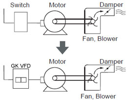 Variable Frequency Drive (VFD) can be used in lots of fields. Variable frequency drives are widely used to control the speed of ...
 Variable Frequency Drive (VFD) can be used in lots of fields. Variable frequency drives are widely used to control the speed of ...
VFD manufacturers
