Home » Applications » VFD in mine industry
VFD in mine industry
Introduction
In mine production, the essential equipment, mine hoister & crane, includes shaft and incline hoists which is treated as the "throat" of the mine. It is responsible for putting down and up of ore, barren rocks, equipment, materials and labors.
One of the mine companies in China, adopted traditional rotor winding resistance to adjust speed by alternating current. This kind of speed regulation method has lots of shortages: first, it takes lots of time in faults determine as there are so many electromagnetic relays, and the failure rate is very high in long time operation, which not only need a high cost in maintenance but also affect the ore production; Second, low hoist automation degree, loud operation noise, high temperature, high labor intensity and the hoist driver get tired easily; Third, in continuous heavy loads lifting in low speed, the resistance get overheat easily, then cause resistance connection wire burning and high energy waste; The last but not limited on these point, the step speed regulation cause huge mechanical impact on the steel wire rope and speed reducer.
1. Transform Solution and System Composition
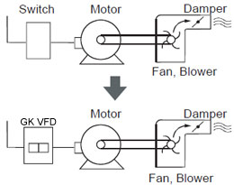
1.1 Transform solution
Replace the original resistance speed regulation system with an AC (alternating current) speed regulation system which is consisted of variable frequency speed regulation device, PLC (programmable logic controller), energy feedback unit and touch screen.
1.2 System Composition
The system composition diagram is shown as FIG. 1:
The variable frequency circuit includes: knife switch, breaker, VFD, contactor under the VFD and energy feedback unit, which, the energy feedback unit composes one cabinet.
Control circuit: consists of main PLC, auxiliary PLC, touch screen, relay auxiliary control and operation panel. The main PLC and auxiliary PLC compensate each other, the relay auxiliary control, main PLC control and auxiliary PLC control are installed in the same control cabinet, and the touch screen is installed on the operation panel as the upper computer. As the feedback signal of location and speed, the encoder is installed in the motor and hoisting drum. The speed-measuring encoder installed in the motor feeds back the signal to the VFD, which constitutes a PG vector control; another encoder feeds back a signal to the PLC to calculate the speed and location. The signals of the speed-measuring motor, oil temperature, oil pressure and other switching values enter the PLC system.
2 System Functions
2.1 Stop, automatic, manual and slide state
Stop: in this state, the system stop working, all of the operations are invalidation, and the winch is under block braking state.
Manual: under the system's safe operation, conduct regular manual operations to control the winch up and down through the master controller.
Automatic: the Up and Down buttons automatically control the whole process of up and down operation, and during its trip, manual intervention can be conducted to stop its motion by pressing the Stop button, and it can be restarted by pressing the Up and Down buttons again.
Slide: When the system has a serious fault and cannot be used with up and down operations, the function switch should be switched to this location, and the winch can slide to the confirmed location through the master controller.
Winch double-wire protection and controls required in the "Safety Regulations for Coal Mines" are realized through double PLC digital control technology. Winch double-wire protection & controls have the following characteristics:
(1) High precision and wide range speed regulation, the speed regulation precision can be as low as 0.05%
(2) Double-wire protection: one hardware safety circuit and two software safety circuits for redundant to each other, which makes the system safer and more reliable.
(3) Double-wire control: during normal operation, due to the double PLC systems which are mutual monitoring and redundant to each other, when one PLC system failed, another PLC system can still be put into use to conduct emergency start, which can improve the operation reliability of the winch system.
2.2 Protection and Interlock Function
2.2.1 During safety braking, coordinate with the safety valves in hydraulic station to realize primary and secondary braking, and the VFD enters into feedback braking state.
2.2.2 In any situation, the hoist/crane only can be operated after the driver received the start signal.
2.2.3 During the hoisting process, if there is a situation like the lubricating oil pressure is too high or too low, or the lubricating oil filter or hydraulic station filter has a blockage or its oil temperature is too high, the touch screen will indicate the corresponding message of failure, and the corresponding information light will be turned on to inform the driver that this hoisting operation can be completed, but the next hoisting operation can only be conducted once the failure point is eliminated.
2.2.4 When the hoist/crane stops during the travel due to failure, and if the hoisting conveyance is within the reduction travel, after the failure has been eliminated, the driver is allowed to choose starting toward the last direction before the stop, and it can only be driven in low speed; if the hoisting conveyance is not within the reduction travel, send start signal at the mine entrance, and allow the driver to drive in high speed.
2.2.5 When the whole mine has a power failure, the PLC system can ensure that the hoister can realize secondary braking, and backup protection of the hoister/crane is also properly done.
2.2.6 The operation braking torque of the disk brake is adjustable. The emergency braking (safety braking) can generate secondary braking to avoid mechanical shock.
2.3 Stroke Control Function
Stroke control is conducted by the PLC system, which mainly divides the lifting process of the hoist into various intervals in accordance with different lifting speeds. Convert the given value of the VFD speed in accordance with the actual situation and different speed requirements of each interval, and form into closed loop to smoothly regulate the lifting speed of the hoist. The stroke control not only controls the speed of the whole lifting process of the hoist, but also the stop and braking process. The stroke control can prevent various accidents of the hoist such as over winding, over discharging, derailment and overturning from happening. It especially applies to special inclined shaft with curves and turnoffs.
2.4 Braking Control Function
The regular braking of the hoister includes feedback braking, contracting braking, etc. Feedback braking is realized by introducing an inverter link into the DC link of the AC-DC-AC voltage type VFD. When the actual operation speed of the crane/hoist is higher than the given operating speed, the ac motor equals a generator, the voltage of the DC link increases, which provides energy to the VFD and feeds back to the power system, and the ac motor automatically operates in a braking state to realize accurate stop of the VFD and also to well prevent mechanic shock and fast slide. Contracting braking is usually used during stops when it moves to the stop position, the process controller sends a stop signal to the VFD, and in the meantime, it also sends contracting control signal to the contracting brake to realize contracting braking. When there is an accident such as derailment, the operation control conducts emergency contracting braking.
The system adopts feedback braking method. During the braking process, the crane/hoister has stable operation and feeds back the braking energy to the power system, which has certain effect of energy conservation. This VFD's braking process is shown as:
3 Functions of Main Components
3.1 PLC (programmable logic controller)
All of system control is achieved by programmable logic controller (PLC) except the emergency protection function. The programmable logic controller equipped in the system can adapt to severe industrial environments, it has a strong anti-interference capacity and two communication ports (programmer port and universal port) which can be used at the same time, it can directly and conveniently show the system operation state, fault state and operation parameters through communication with the liquid crystal touch screen, and it can also show the state of all switching elements as well as information of failure and alarm; signals sent from the voltage transducer, current transducer and encoder equipped in the receiving system will be used to conduct control, monitoring and protection of the winch after calculation and processing. During emergency braking (safe braking), the PLC (programmable logic controller) controls the disk brake to generate secondary braking to avoid mechanic shock. FIG. 2 has shown the control flow diagram of the PLC (programmable logic controller) of a simplified system.
3.2 VFD
The VFD receives speed feedback signal from the rotary encoder, forms PG vector control, and realizes stepless speed regulation of the ac motor. This system is consisted of VFD and energy feedback unit.
- Integrate solution: combine motor driven and lift logic control, save the PLC of the original system, reduce potential failure spots, simplify system wiring and flexible debugging, which presents the future development direction of hoist control;
- Wide input voltage range can better satisfy severe power environment;
- Professional hoist logic design: based on many years' design experience in the hoist/crane industry, design as safety logic control with expert-level and widely used hoisting structure, including functions such as timing coordination and anti-running, and a perfect solution will be provided to the customers;
- Special fixed-length design for the loading system in mining, metallurgy and road-building industries, which makes the control safer and more reliable. Accurate torque control: stall prevention function and failure resetting and retrying function; installation and application of the rotary encoder can realize vector control of flux current in the whole frequency domain, and output 150% torque for the ac motor in 0.5Hz.
The VFD main technical parameters:
(1) Input power voltage is 304-456VAC, 50Hz; voltage fluctuate range +/-20%, frequency fluctuate range is 48-65HZ;
(2) Continuously adjustable of the output frequency within 0~50Hz;
(3) Output rated heavy load power: 160kW;
(4) Overload capacity: 150%, 1 minute; 180%, 20 seconds;
(5) High power factor, cosf>0.98;
(6) Automatic torque boosting function and slip compensation function in low-frequency operation, ensure 150% rated torque;
(7) The VFD has over-voltage, under-voltage, over-current, overload, components overheating and lack-phase protection for the ac motor, has failure memory function which can save the latest 5 failed functional codes and the last failed parameter.
(8) Total harmonic content THD < 5%.
Main technical principles
(1) All-digital speed sensor closed-loop vector control to provide a wide range and high precision for the system speed regulation. When the VFD operates under low frequency and can ensure more than 150 % of rated torque. The maximum torque is twice to the rated torque. The basic principle to realize vector control is to first measure and control the stator current vector of the asynchronous motor and then control the exciting current and torque current of the asynchronous motor in accordance with the field orientation theory, in this way realizing the purpose of controlling the torque of the asynchronous motor. The specific procedure is to divide the stator current vector of asynchronous motor into the current component (exciting current) which can generate a magnetic field and the current component (torque current) which can generate torque, and in the meantime, control the amplitude and phase of these two components, i.e., control the stator current vector, and this control mode is called vector control mode. In this way, a three-phase asynchronous motor can be controlled like a DC motor, and static and dynamic performances same as a DC speed regulation system can be obtained.
PLC control procedure is shown in FIG. 2.
3.3 Energy Feedback Unit
The main purpose is to increase the braking capacity of the VFD, and feedback the braking energy to the power system when the winch puts down heavy weights for energy conservation.
3.4 Operation panel
The operation panel is installed with a manually operated master controller, regulates the braking force and operation speed of the winch manually, contains manual and pedal emergency braking switch for fast breaking in emergency situation.
3.5 Touch screen
Through communication with PLC (programmable logic controller), it can directly show the system operation state, fault state and operation parameters (such as the operation speed of the winch, location of the hoisting conveyance, motor current and voltage, etc.), it can show the state of all switching elements as well as various failures and alarm information, it can modify the internal parameter setting of PLC (it requires corresponding authority), it has password protection function, which can modify the operator password in accordance with setting of authority, and operators with different security levels have different operation authorities.
4. Main components selection
4.1. VFD
AC motor: JR 127- 8 115k W
Rated voltage: 380V
Rated current: 227A
In accordance with the principle: VFD rated output current = ac motor rated current×1.1
227×1.1=249.7A
VFD:
Capacity 132k VA with 255A rated output current
Capacity 160k VA with 302A rated output current
Considering both the mine environment and the transportation condition, choose the I60k VA VFD.
4.2 PLC (programmable logic controller)
Through comprehensive consideration of up over-winding, down over-winding, manual up, manual down, automatic up, automatic down, normal stop, emergency stop, safety circuit, hydraulic station control, disc valve control, various operation indicators and backup indicators as well as mutual interlock between various operating modes and certain redundancy, finally choose Mitsubishi PLC (programmable logic controller) with 48 points.
Model: FX2N-48M-001
4.3 Energy feedback unit
4.3.1 Braking Voltage
If the chosen braking voltage is too low, when the voltage of the power system increases, it's easy to cause malfunction of the braking unit. If the chosen braking voltage is high, it's easy to cause threat to the safe operation of equipment. For a 380V system, a 700V braking voltage is the right selection.
4.3.2 Braking Current
Braking current is defined as the DC current flowing through the brake resistor and brake unit in braking state.
Basis of selection: the braking must be able to absorb all the renewable energy of the ac motor.
Braking absorption power (U×I) = renewable energy of the motor (watt)=1000×P×?
P____ Motor rated power (kW)
U____DC operating point of the braking unit, it is generally 700V
I____ Braking current (A)
?____ Conversion efficiency of mechanical energy during feedback, and generally take ?=0.7
Through calculation, we get: I=115
4.3.3 Power Selection
The renewable energy of the ac motor must be absorbed and feed back to the power system.
PR=P×Kf×?×e
PR____Power of the feedback unit (Kw)
?____ Conversion efficiency of mechanical energy during feedback, and generally take ?=0.7
e____ Braking power consumption safety coefficient, take e =1.4
Kf____ Braking frequency, means time proportion of the regenerative process in the whole operation of the ac motor
Referring to related documents the Kf take 60%
Calculate to PR =67.62 kW
Feedback unit power choose 70 kW
5. Transform efficiency
5.1. Operation
After the system has been put into operation, the winch operates more convenient and runs more stable, the temperature and noise of the winch control room have been greatly improved, which provides a great environment for the operator.
5.2. Energy saving
During January to May of 2008, the hoisting unit consumption was 2.92 kilowatt hour/t; during January to May of 2009, the hoisting unit consumption was 1.66 kilowatt hour/t. The unit consumption had decreased by 1.26 kilowatt hour/t, and the decrease rate of unit consumption was 43.15%. In 2008, 132,334 tons of ores were lifted, 166,700 kilowatt hours of electricity were saved, and in accordance with the electricity price of RMB 0.528yuan/ kilowatt hour, an electricity cost of 88,040 Yuan has been saved.
6. Conclusion
The variable frequency drive in shaft hoist system can solve speed regulation and start problems, realize soft start and soft stop, reduce mechanical shock and make operation more stable and reliable; the impulse current during start and acceleration shifting is smaller, which has a reduced impact on the power system, simplified operation and reduced labor intensity of the workers; the operation speed curve presents a S-shape, which makes the acceleration and deceleration smoother without impact sensitivity; it has complete safety protection functions, and in addition to common protection against over-voltage, under-voltage, overload, short circuit and temperature rise, it is also equipped with interlock protection and automatic speed-limit protection. In the hoist/crane used in the inclined shaft, the variable frequency speed regulation system is used to replace the series resistance speed regulation system, which is a new approach to increase the technology content of crane/hoist used in inclined shaft of mine and also to explore new way of energy saving.
In mine production, the essential equipment, mine hoister & crane, includes shaft and incline hoists which is treated as the "throat" of the mine. It is responsible for putting down and up of ore, barren rocks, equipment, materials and labors.
One of the mine companies in China, adopted traditional rotor winding resistance to adjust speed by alternating current. This kind of speed regulation method has lots of shortages: first, it takes lots of time in faults determine as there are so many electromagnetic relays, and the failure rate is very high in long time operation, which not only need a high cost in maintenance but also affect the ore production; Second, low hoist automation degree, loud operation noise, high temperature, high labor intensity and the hoist driver get tired easily; Third, in continuous heavy loads lifting in low speed, the resistance get overheat easily, then cause resistance connection wire burning and high energy waste; The last but not limited on these point, the step speed regulation cause huge mechanical impact on the steel wire rope and speed reducer.
1. Transform Solution and System Composition
1.1 Transform solution
Replace the original resistance speed regulation system with an AC (alternating current) speed regulation system which is consisted of variable frequency speed regulation device, PLC (programmable logic controller), energy feedback unit and touch screen.
1.2 System Composition
The system composition diagram is shown as FIG. 1:
The variable frequency circuit includes: knife switch, breaker, VFD, contactor under the VFD and energy feedback unit, which, the energy feedback unit composes one cabinet.
Control circuit: consists of main PLC, auxiliary PLC, touch screen, relay auxiliary control and operation panel. The main PLC and auxiliary PLC compensate each other, the relay auxiliary control, main PLC control and auxiliary PLC control are installed in the same control cabinet, and the touch screen is installed on the operation panel as the upper computer. As the feedback signal of location and speed, the encoder is installed in the motor and hoisting drum. The speed-measuring encoder installed in the motor feeds back the signal to the VFD, which constitutes a PG vector control; another encoder feeds back a signal to the PLC to calculate the speed and location. The signals of the speed-measuring motor, oil temperature, oil pressure and other switching values enter the PLC system.
2 System Functions
2.1 Stop, automatic, manual and slide state
Stop: in this state, the system stop working, all of the operations are invalidation, and the winch is under block braking state.
Manual: under the system's safe operation, conduct regular manual operations to control the winch up and down through the master controller.
Automatic: the Up and Down buttons automatically control the whole process of up and down operation, and during its trip, manual intervention can be conducted to stop its motion by pressing the Stop button, and it can be restarted by pressing the Up and Down buttons again.
Slide: When the system has a serious fault and cannot be used with up and down operations, the function switch should be switched to this location, and the winch can slide to the confirmed location through the master controller.
Winch double-wire protection and controls required in the "Safety Regulations for Coal Mines" are realized through double PLC digital control technology. Winch double-wire protection & controls have the following characteristics:
(1) High precision and wide range speed regulation, the speed regulation precision can be as low as 0.05%
(2) Double-wire protection: one hardware safety circuit and two software safety circuits for redundant to each other, which makes the system safer and more reliable.
(3) Double-wire control: during normal operation, due to the double PLC systems which are mutual monitoring and redundant to each other, when one PLC system failed, another PLC system can still be put into use to conduct emergency start, which can improve the operation reliability of the winch system.
2.2 Protection and Interlock Function
2.2.1 During safety braking, coordinate with the safety valves in hydraulic station to realize primary and secondary braking, and the VFD enters into feedback braking state.
2.2.2 In any situation, the hoist/crane only can be operated after the driver received the start signal.
2.2.3 During the hoisting process, if there is a situation like the lubricating oil pressure is too high or too low, or the lubricating oil filter or hydraulic station filter has a blockage or its oil temperature is too high, the touch screen will indicate the corresponding message of failure, and the corresponding information light will be turned on to inform the driver that this hoisting operation can be completed, but the next hoisting operation can only be conducted once the failure point is eliminated.
2.2.4 When the hoist/crane stops during the travel due to failure, and if the hoisting conveyance is within the reduction travel, after the failure has been eliminated, the driver is allowed to choose starting toward the last direction before the stop, and it can only be driven in low speed; if the hoisting conveyance is not within the reduction travel, send start signal at the mine entrance, and allow the driver to drive in high speed.
2.2.5 When the whole mine has a power failure, the PLC system can ensure that the hoister can realize secondary braking, and backup protection of the hoister/crane is also properly done.
2.2.6 The operation braking torque of the disk brake is adjustable. The emergency braking (safety braking) can generate secondary braking to avoid mechanical shock.
2.3 Stroke Control Function
Stroke control is conducted by the PLC system, which mainly divides the lifting process of the hoist into various intervals in accordance with different lifting speeds. Convert the given value of the VFD speed in accordance with the actual situation and different speed requirements of each interval, and form into closed loop to smoothly regulate the lifting speed of the hoist. The stroke control not only controls the speed of the whole lifting process of the hoist, but also the stop and braking process. The stroke control can prevent various accidents of the hoist such as over winding, over discharging, derailment and overturning from happening. It especially applies to special inclined shaft with curves and turnoffs.
2.4 Braking Control Function
The regular braking of the hoister includes feedback braking, contracting braking, etc. Feedback braking is realized by introducing an inverter link into the DC link of the AC-DC-AC voltage type VFD. When the actual operation speed of the crane/hoist is higher than the given operating speed, the ac motor equals a generator, the voltage of the DC link increases, which provides energy to the VFD and feeds back to the power system, and the ac motor automatically operates in a braking state to realize accurate stop of the VFD and also to well prevent mechanic shock and fast slide. Contracting braking is usually used during stops when it moves to the stop position, the process controller sends a stop signal to the VFD, and in the meantime, it also sends contracting control signal to the contracting brake to realize contracting braking. When there is an accident such as derailment, the operation control conducts emergency contracting braking.
The system adopts feedback braking method. During the braking process, the crane/hoister has stable operation and feeds back the braking energy to the power system, which has certain effect of energy conservation. This VFD's braking process is shown as:
3 Functions of Main Components
3.1 PLC (programmable logic controller)
All of system control is achieved by programmable logic controller (PLC) except the emergency protection function. The programmable logic controller equipped in the system can adapt to severe industrial environments, it has a strong anti-interference capacity and two communication ports (programmer port and universal port) which can be used at the same time, it can directly and conveniently show the system operation state, fault state and operation parameters through communication with the liquid crystal touch screen, and it can also show the state of all switching elements as well as information of failure and alarm; signals sent from the voltage transducer, current transducer and encoder equipped in the receiving system will be used to conduct control, monitoring and protection of the winch after calculation and processing. During emergency braking (safe braking), the PLC (programmable logic controller) controls the disk brake to generate secondary braking to avoid mechanic shock. FIG. 2 has shown the control flow diagram of the PLC (programmable logic controller) of a simplified system.
3.2 VFD
The VFD receives speed feedback signal from the rotary encoder, forms PG vector control, and realizes stepless speed regulation of the ac motor. This system is consisted of VFD and energy feedback unit.
- Integrate solution: combine motor driven and lift logic control, save the PLC of the original system, reduce potential failure spots, simplify system wiring and flexible debugging, which presents the future development direction of hoist control;
- Wide input voltage range can better satisfy severe power environment;
- Professional hoist logic design: based on many years' design experience in the hoist/crane industry, design as safety logic control with expert-level and widely used hoisting structure, including functions such as timing coordination and anti-running, and a perfect solution will be provided to the customers;
- Special fixed-length design for the loading system in mining, metallurgy and road-building industries, which makes the control safer and more reliable. Accurate torque control: stall prevention function and failure resetting and retrying function; installation and application of the rotary encoder can realize vector control of flux current in the whole frequency domain, and output 150% torque for the ac motor in 0.5Hz.
The VFD main technical parameters:
(1) Input power voltage is 304-456VAC, 50Hz; voltage fluctuate range +/-20%, frequency fluctuate range is 48-65HZ;
(2) Continuously adjustable of the output frequency within 0~50Hz;
(3) Output rated heavy load power: 160kW;
(4) Overload capacity: 150%, 1 minute; 180%, 20 seconds;
(5) High power factor, cosf>0.98;
(6) Automatic torque boosting function and slip compensation function in low-frequency operation, ensure 150% rated torque;
(7) The VFD has over-voltage, under-voltage, over-current, overload, components overheating and lack-phase protection for the ac motor, has failure memory function which can save the latest 5 failed functional codes and the last failed parameter.
(8) Total harmonic content THD < 5%.
Main technical principles
(1) All-digital speed sensor closed-loop vector control to provide a wide range and high precision for the system speed regulation. When the VFD operates under low frequency and can ensure more than 150 % of rated torque. The maximum torque is twice to the rated torque. The basic principle to realize vector control is to first measure and control the stator current vector of the asynchronous motor and then control the exciting current and torque current of the asynchronous motor in accordance with the field orientation theory, in this way realizing the purpose of controlling the torque of the asynchronous motor. The specific procedure is to divide the stator current vector of asynchronous motor into the current component (exciting current) which can generate a magnetic field and the current component (torque current) which can generate torque, and in the meantime, control the amplitude and phase of these two components, i.e., control the stator current vector, and this control mode is called vector control mode. In this way, a three-phase asynchronous motor can be controlled like a DC motor, and static and dynamic performances same as a DC speed regulation system can be obtained.
PLC control procedure is shown in FIG. 2.
3.3 Energy Feedback Unit
The main purpose is to increase the braking capacity of the VFD, and feedback the braking energy to the power system when the winch puts down heavy weights for energy conservation.
3.4 Operation panel
The operation panel is installed with a manually operated master controller, regulates the braking force and operation speed of the winch manually, contains manual and pedal emergency braking switch for fast breaking in emergency situation.
3.5 Touch screen
Through communication with PLC (programmable logic controller), it can directly show the system operation state, fault state and operation parameters (such as the operation speed of the winch, location of the hoisting conveyance, motor current and voltage, etc.), it can show the state of all switching elements as well as various failures and alarm information, it can modify the internal parameter setting of PLC (it requires corresponding authority), it has password protection function, which can modify the operator password in accordance with setting of authority, and operators with different security levels have different operation authorities.
4. Main components selection
4.1. VFD
AC motor: JR 127- 8 115k W
Rated voltage: 380V
Rated current: 227A
In accordance with the principle: VFD rated output current = ac motor rated current×1.1
227×1.1=249.7A
VFD:
Capacity 132k VA with 255A rated output current
Capacity 160k VA with 302A rated output current
Considering both the mine environment and the transportation condition, choose the I60k VA VFD.
4.2 PLC (programmable logic controller)
Through comprehensive consideration of up over-winding, down over-winding, manual up, manual down, automatic up, automatic down, normal stop, emergency stop, safety circuit, hydraulic station control, disc valve control, various operation indicators and backup indicators as well as mutual interlock between various operating modes and certain redundancy, finally choose Mitsubishi PLC (programmable logic controller) with 48 points.
Model: FX2N-48M-001
4.3 Energy feedback unit
4.3.1 Braking Voltage
If the chosen braking voltage is too low, when the voltage of the power system increases, it's easy to cause malfunction of the braking unit. If the chosen braking voltage is high, it's easy to cause threat to the safe operation of equipment. For a 380V system, a 700V braking voltage is the right selection.
4.3.2 Braking Current
Braking current is defined as the DC current flowing through the brake resistor and brake unit in braking state.
Basis of selection: the braking must be able to absorb all the renewable energy of the ac motor.
Braking absorption power (U×I) = renewable energy of the motor (watt)=1000×P×?
P____ Motor rated power (kW)
U____DC operating point of the braking unit, it is generally 700V
I____ Braking current (A)
?____ Conversion efficiency of mechanical energy during feedback, and generally take ?=0.7
Through calculation, we get: I=115
4.3.3 Power Selection
The renewable energy of the ac motor must be absorbed and feed back to the power system.
PR=P×Kf×?×e
PR____Power of the feedback unit (Kw)
?____ Conversion efficiency of mechanical energy during feedback, and generally take ?=0.7
e____ Braking power consumption safety coefficient, take e =1.4
Kf____ Braking frequency, means time proportion of the regenerative process in the whole operation of the ac motor
Referring to related documents the Kf take 60%
Calculate to PR =67.62 kW
Feedback unit power choose 70 kW
5. Transform efficiency
5.1. Operation
After the system has been put into operation, the winch operates more convenient and runs more stable, the temperature and noise of the winch control room have been greatly improved, which provides a great environment for the operator.
5.2. Energy saving
During January to May of 2008, the hoisting unit consumption was 2.92 kilowatt hour/t; during January to May of 2009, the hoisting unit consumption was 1.66 kilowatt hour/t. The unit consumption had decreased by 1.26 kilowatt hour/t, and the decrease rate of unit consumption was 43.15%. In 2008, 132,334 tons of ores were lifted, 166,700 kilowatt hours of electricity were saved, and in accordance with the electricity price of RMB 0.528yuan/ kilowatt hour, an electricity cost of 88,040 Yuan has been saved.
6. Conclusion
The variable frequency drive in shaft hoist system can solve speed regulation and start problems, realize soft start and soft stop, reduce mechanical shock and make operation more stable and reliable; the impulse current during start and acceleration shifting is smaller, which has a reduced impact on the power system, simplified operation and reduced labor intensity of the workers; the operation speed curve presents a S-shape, which makes the acceleration and deceleration smoother without impact sensitivity; it has complete safety protection functions, and in addition to common protection against over-voltage, under-voltage, overload, short circuit and temperature rise, it is also equipped with interlock protection and automatic speed-limit protection. In the hoist/crane used in the inclined shaft, the variable frequency speed regulation system is used to replace the series resistance speed regulation system, which is a new approach to increase the technology content of crane/hoist used in inclined shaft of mine and also to explore new way of energy saving.
Post a Comment:
You may also like:
Featured Articles
Variable frequency drive application ...
 Variable Frequency Drive (VFD) can be used in lots of fields. Variable frequency drives are widely used to control the speed of ...
Variable Frequency Drive (VFD) can be used in lots of fields. Variable frequency drives are widely used to control the speed of ...
VFD manufacturers