Home » FAQ
The basic consideration is how close the variable frequency drive (VFD) output waveform approximates a true sinusoid. Most modern VFDs produce reasonable approximations - if viewed from a "macro" perspective. But when we zoom in to specific instances and pulses, we see there is always some amount of voltage over/undershoot occurring. And VFDs which contain an intermediate DC bus (which is pretty much a given, if the input and output are AC at different frequencies) will often have what is called a "common mode" voltage. This tends to elevate the neutral plane (on the motor side) by some amount - resulting in additional stress on the motor winding insulation.
Anything which distorts the waveform from a true sinusoid - and a true neutral - will negatively impact the insulation system through increased heating or voltage stress. Either way, the motor system has to accommodate the VFD output - so the system is designed differently.
if viewed from a "macro" perspective. But when we zoom in to specific instances and pulses, we see there is always some amount of voltage over/undershoot occurring. And VFDs which contain an intermediate DC bus (which is pretty much a given, if the input and output are AC at different frequencies) will often have what is called a "common mode" voltage. This tends to elevate the neutral plane (on the motor side) by some amount - resulting in additional stress on the motor winding insulation.Anything which distorts the waveform from a true sinusoid - and a true neutral - will negatively impact the insulation system through increased heating or voltage stress. Either way, the motor system has to accommodate the VFD output - so the system is designed differently.
I have delta connected capacitor banks with Auto Power Factor Controller on 440 V bus. Also motors are connected on the same bus with VFDs for starting. The question is that is there any harmful effect on the VFDs due to capacitor switching (in steps)? Does using a synchronous motor for reactive power control much better due to its smooth control?
 If the variable frequency drive (motor and supply cabling) is protected by fuses, we normally assume that the fuses will have sufficient interruption capacity to act as a protection device in their own right, without any additional circuit breaker.
 If the VFD is protected through a circuit breaker (mechanical contacts, controlled by some bi-metallic device, or an over-current relay), the contacts of this circuit breaker must be rated to withstand breaking of the highest current that can occur under operation of the VFD. This means, that it must typically be rated to interrupt the full short-circuit current that can occur on the busbars on the SUPPLY side of the breaker. The contact rating of this device may have to be many times the maximum possible current for the VFD itself. This value is not dependent on any rating of the VFD itself, except in the very few situations where it may have been installed at the motor end of the cable supplying the VFD. In this case, there must be some additional protection for the cable, at the supply point.
The two technologies are very different, and if there is a need for speed control, then a variable frequency drive (VFD) should be selected. If however, there is no requirement for speed control, then a soft starter is a very good alternative selection, this is the basic difference. In fact, at real life applications, the ratio of VFD applications to soft starter applications is in the order of one VFD compare to every four to five soft starters. Indeed, that is about the ratio that we supply industry in general.
I would suggest that you could use a VFD in almost every application to replace a soft starter if you were prepared to pay the extra capital cost, plus the extra running cost, plus the extra harmonic mitigation costs. While you may not be seeing it, down here we are having major issues with harmonics from VFDs. up to 16% THDv due to the number of installed VFDs. Harmonic mitigation is now mandatory.
I would suggest that you could use a VFD in almost every application to replace a soft starter if you were prepared to pay the extra capital cost, plus the extra running cost, plus the extra harmonic mitigation costs. While you may not be seeing it, down here we are having major issues with harmonics from VFDs. up to 16% THDv due to the number of installed VFDs. Harmonic mitigation is now mandatory.
Single phase variable frequency drive can convert from single phase input to three phase output, but the maximum output voltage is equal to input voltage. In the case, you may need a transformer. The transformer convert single phase 240V to three phase 415V. If you don't need to control the motor speed, then no need a VFD at all.
We ordered a VFD for 220V but it would take too long to get this one. Therefore the people of Gozuk in China gave us a variable frequency drive for 380V with a good discount. This made that we could start experimenting the next day after ordering. But because of the high voltage it wasn't save and/or smart to work alone at the practical experiments. Christer, my colleague, had only time at Thursday and Friday so this became a problem. That's why we hadn't the chance to do many experiments. We were pretty excited about a DC connection we established. We actually drove the motor on DC voltage.
No form of dynamic braking operates as a holding brake. Holding must be accomplished with a mechanical brake. The dynamic braking resistor is a dumping ground for the energy contained in the rotating system, allowing it to be "bled off" as electrical energy. Because the operational mode has changed from motoring (power flow from VFD source to machine) to generating (from rotating machine to VFD), the variable frequency drive must be capable of supplying power in both directions.
If you're not seeing obvious ESD damage, the bearing life problem is likely not directly variable frequency drive (VFD) related, especially if some of the bearings are insulated. It has been my experience that whatever the most complicated piece of equipment in the system, that's what gets blamed, and VFD falls into that category.
If the bearing failures are not obviously ESD-related, what characteristics are you seeing? Are they consistent over the horsepower range of your motors? Are you operating the same switching or carrier frequency on the variable frequency drive? Have you attempted varying the lubricant? What is the ambient temperature range at the machine? Answers to these questions would lead you some very good suggestions.
If the bearing failures are not obviously ESD-related, what characteristics are you seeing? Are they consistent over the horsepower range of your motors? Are you operating the same switching or carrier frequency on the variable frequency drive? Have you attempted varying the lubricant? What is the ambient temperature range at the machine? Answers to these questions would lead you some very good suggestions.
Adding a separate fan improves motor efficiency but system efficiency reduces. It is important to consider the power input external fan motor also while calculating efficiency. In most of the cases people do not like to go for separate fan as it reduces reliability of the motor system. Separate fan is used for variable speed motors where the speed variation is from 0 to rated or higher speed.
First measure the air velocity on the surface motor at cowl exit or variable speed drive end using a velometer. (Quantity of air is given by product of air velocity at air inlet and area of air inlet). Once you get the velocity you need to carry out few experiments with different fans as we do not know whether the fan in the motor is optimal one. There is a band of velocities for which the cooling will be optimum. Too low a velocity or too high a velocity can increase the motor temperature.
First measure the air velocity on the surface motor at cowl exit or variable speed drive end using a velometer. (Quantity of air is given by product of air velocity at air inlet and area of air inlet). Once you get the velocity you need to carry out few experiments with different fans as we do not know whether the fan in the motor is optimal one. There is a band of velocities for which the cooling will be optimum. Too low a velocity or too high a velocity can increase the motor temperature.
My thought was that they were promoting what many are calling "Flux Braking", which, like variable frequency drive DC Injection Braking, converts the kinetic energy in the moving load to heat energy INSIDE of the motor, but like Dynamic Braking and Regenerative Braking, it starts by pulling energy OFF of the motor as electricity by putting it into Regenerative mode. The difference is in what happens to that nerdy once it is in the DC bus link. In Dynamic Braking, that energy is fired off into a resistor bank and burned off as heat, removing it from the motor. In Line Regenerative Braking, that energy in the vfd DC bus is pumped back into the line source through an Active Front End (AFE), or in some cases a less complex Fundamental Front End (FFE), both of which ALSO removes the energy from the circuit.
The worst thing that can happen is a failure to the VFD power section. This can happen in two situations: if line power applied to the VFD is higher than the VFD rating (i.e. 600 Vac line power is applied to a 240 V ac rated VFD), or if the VFD is miswired such that input line power is connected to the output terminals. Unfortunately, both of these scenarios are fairly common and are usually due to haste in installation. This is why VFD manufacturers urge users to read and understand all the ratings and installation procedures before attempting to wire the VFD.
4-20ma advantages:
The 4 ma "bottom of span" signal allows the receiver to detect a broken wire. Since the loop current never falls to zero, can be loop powered, allowing for two-wire. 20 ma is low enough to be made intrinsically safe, in most locations.
The constant-current feature of a current loop cancels out voltage drop errors due to long wiring runs (of course this would also be true if you selected different current values for zero and span).
Featured Articles
Non-Enclosure Variable Frequency Drive ...
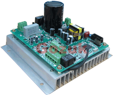 No enclosure (cover), reducing installation space and cost effective. Widely used in All-In-One control cabinet. Keep the same ...
No enclosure (cover), reducing installation space and cost effective. Widely used in All-In-One control cabinet. Keep the same ...Variable frequency drive application ...
 Variable Frequency Drive (VFD) can be used in lots of fields. Variable frequency drives are widely used to control the speed of ...
Variable Frequency Drive (VFD) can be used in lots of fields. Variable frequency drives are widely used to control the speed of ...Variable frequency drive in HVAC ...
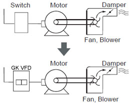
 Variable frequency drives (VFD) have been used for HVAC systems in buildings for more than 40 years. But only in recent years, ...
Variable frequency drives (VFD) have been used for HVAC systems in buildings for more than 40 years. But only in recent years, ...Variable Frequency Drive Harmonics and ...
A discussion of the benefits of variable frequency drives often leads to a question regarding electrical harmonic distortion ...
Three phase inverters
 In the variable frequency drive rectifier paper, it explains how to go from three phase alternating current voltage to a direct ...
In the variable frequency drive rectifier paper, it explains how to go from three phase alternating current voltage to a direct ...
VFD manufacturers