Home » Troubleshooting
If we are having a dual drive philosophy for a fan/blower - arrangement is such that VFD driven motor is in operation and there is a standby motor (Direct on line starter) on the same shaft with declutch arrangement. Will it be possible for the standby motor to take full load in case VFD driven motor trip with in say 7-10 seconds? If yes what is the best possible arrangement/solution for such critical application if we want to avoid the trip. If anyone having idea about over-running or freewheeling movement (with clutch armament) - which one is recommended and what are the pros and cons of each philosophy.
The three phase voltage supplied by the PWM variable frequency drive, differently from a purely sinusoidal voltage, is not balanced. That is, owing to the variable frequency drive stage topology, the vector sum of the instantaneous voltages of the three phases at the variable frequency drive output does not cancel out, but results in a high frequency electric potential relative to a common reference value (usually the earth or the negative bus of the DC link), hence the denomination "common mode".

The sum of the instantaneous voltage values at the (three phase) variable frequency drive output does not equal to zero.
This high frequency common mode voltage may result in undesirable common mode currents. Existing stray capacitances between motor and earth thus may allow current flowing to the earth, passing through rotor, shaft and bearings and reaching the end shield (earthed).
Put a braking resistor on variable frequency drive. If the VFD has provisions for DC Bus voltage control utilizing an external resistor, buy the resistor and install it. If the variable frequency drive does not have that control, it can be added as an option package on most drive models. Otherwise the only way to compensate for this is to change the variable frequency drive parameters to prevent the VFD from decelerating the motor too quickly causing the regeneration which jacks up the bus voltage.
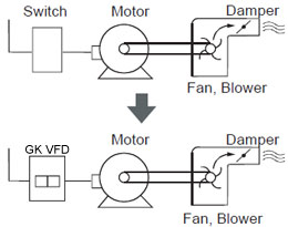
One move that has already found support across the broad spectrum of operators, suppliers, government agencies and industry bodies is the use of VFDs. These VFDs can be used to run a plants AC motors, which previously might have been operated at constant speed all the time. With the DOE estimating that some 18% of the energy consumed by the nations industrial motors could be saved by switching to energy efficient technologies, such as variable frequency drives, it would seem to be an open and shut case in their favor. And, so it has proved in most applications. Occasionally, though, running an AC motor off a variable frequency drive can lead to problems that many a process engineer might not have come across before.
The operation of VFDs often results in a technical compatibility problem with residual current circuit breakers. Energy-saving VFDs are increasingly used in building services engineering in conjunction with residual current circuit breakers. For personal protection against electric shocks, 30 mA residual current circuit breakers are prescribed here.
The use of residual current circuit breakers with a threshold value of 300 mA is prescribed in plants in the paper and wood working industry to protect against electric fires (caused by undesirable earth currents). Even when Energy saving VFDs are used correctly, incorrect tripping of residual current circuit breakers is also caused by elevated leakage currents induced by VFD operating conditions, as the circuit breakers cannot distinguish between leakage currents and genuine residual currents. In addition to leakage currents at system frequency, VFDs also generate earth currents dependent on the length of the motor cable, the parasitic capacitance of the motors and the switching frequency set. Unnecessary responses of residual current circuit breakers incur significant cost due to production loss and downtimes of production plants.
The use of residual current circuit breakers with a threshold value of 300 mA is prescribed in plants in the paper and wood working industry to protect against electric fires (caused by undesirable earth currents). Even when Energy saving VFDs are used correctly, incorrect tripping of residual current circuit breakers is also caused by elevated leakage currents induced by VFD operating conditions, as the circuit breakers cannot distinguish between leakage currents and genuine residual currents. In addition to leakage currents at system frequency, VFDs also generate earth currents dependent on the length of the motor cable, the parasitic capacitance of the motors and the switching frequency set. Unnecessary responses of residual current circuit breakers incur significant cost due to production loss and downtimes of production plants.
By using a variable frequency drive to control the acceleration, and in some cases the deceleration, of the driven equipment to acceptable rates, mechanical shock loading and wear to the equipment can be reduced or eliminated.
An example where this has been implemented is in overland conveyors where the torque applied to the driving pulleys is controlled to a given defined maximum value so that the maximum tension in the conveyor belt is limited. If the speed of the conveyor is also controlled so that the specific loading of the belt is limited and controlled, then the belt will run at much slower speeds during reduced throughput, leading to longer intervals between bearing replacements on pulleys and idlers.
An example where this has been implemented is in overland conveyors where the torque applied to the driving pulleys is controlled to a given defined maximum value so that the maximum tension in the conveyor belt is limited. If the speed of the conveyor is also controlled so that the specific loading of the belt is limited and controlled, then the belt will run at much slower speeds during reduced throughput, leading to longer intervals between bearing replacements on pulleys and idlers.
Most variable frequency drives come equipped with self-diagnostic controls to help trace the source of problems. Always observe the following precautions when troubleshooting the VFD:
- Stop the VFD.
- Disconnect, tag, lock out AC power before working on the VFD.
- Verify that there is no voltage present at the AC input power terminals. It's important to remember that DC bus capacitors retain hazardous voltages after input power has been disconnected. Therefore, wait 5 minutes for the DC bus capacitors to discharge once power has been disconnected. Check the voltage with a voltmeter to ensure that the capacitors have discharged before touching any internal components.
- LEDs provide a quick indication of problems.
- Normally, a steady glowing light means everything is running properly. Flashing yellow or red lights indicate a problem with the VFD that should be checked.
The VFD rectifies the incoming AC line to produce a DC voltage that feeds and inverter stage consisting of 6 IGBT switches. The switches are operated to create a pulse width modulated (PWM) output voltage between the M1/M2/M3 output terminals. The voltage between the output terminals provides the necessary variable frequency and variable voltage power source to operate the motor over a wide speed range.
A side effect of the PWM process is that there is also a voltage generated between an imaginary star point on the 3 phases feeding the motor (M1/M2/M3) and the star point of the incoming AC supply.

A side effect of the PWM process is that there is also a voltage generated between an imaginary star point on the 3 phases feeding the motor (M1/M2/M3) and the star point of the incoming AC supply.
Featured Articles
Non-Enclosure Variable Frequency Drive ...
 No enclosure (cover), reducing installation space and cost effective. Widely used in All-In-One control cabinet. Keep the same ...
No enclosure (cover), reducing installation space and cost effective. Widely used in All-In-One control cabinet. Keep the same ...Variable frequency drive application ...
 Variable Frequency Drive (VFD) can be used in lots of fields. Variable frequency drives are widely used to control the speed of ...
Variable Frequency Drive (VFD) can be used in lots of fields. Variable frequency drives are widely used to control the speed of ...Variable frequency drive in HVAC ...
 Variable frequency drives (VFD) have been used for HVAC systems in buildings for more than 40 years. But only in recent years, ...
Variable frequency drives (VFD) have been used for HVAC systems in buildings for more than 40 years. But only in recent years, ...Variable Frequency Drive Harmonics and ...
A discussion of the benefits of variable frequency drives often leads to a question regarding electrical harmonic distortion ...
Three phase inverters
 In the variable frequency drive rectifier paper, it explains how to go from three phase alternating current voltage to a direct ...
In the variable frequency drive rectifier paper, it explains how to go from three phase alternating current voltage to a direct ...
VFD manufacturers