Variable Frequency Drive Bypass
This is an interesting topic with many twists and turns. On the face of it bypassing a VFD seems straight forward enough, or is it? First ask yourself a few questions.
What function does the VFD perform?
Given in this instance that the VFD was designed into the system from the start, it follows that the fuses or circuit breakers selected for the VFDs low starting current characteristics may not be adequate for conventional DOL starting duty.
In bypass will there be adequate motor thermal protection, previously provided by the VFD?
Bear in mind that the primary process control and or energy saving is lost in bypass situations. OK let’s assume that the VFD was not engineered and designed into the original system but was retrofitted at a later stage and that the existing power cables and original starting arrangements have stayed in place. So in the event of a bypass the original thermal overloads would, subject to appropriate calibration be available to protect the motor.
All well and good but what about the ancillary considerations mentioned above, including the loss of primary process control and or energy savings in bypass.
Is the VFD to be bypassed for maintenance and servicing?
Sometimes with good intent, VFDs are arranged with bypass provisions as part of their design with the intention that routine maintenance and servicing can be carried out to the VFD without loss of mission critical functionality. Great idea but how will the VFD be isolated to allow this to happen?
Ordinary contactors on the input and output of a VFD as part of a bypass system do not normally comply with the AS3000 (Wiring rules) requirements for isolation devices.
If the intent is to allow access to the VFD for maintenance during bypass operation, then appropriate switchgear and proper physical segregation arrangements are mandatory for personal safety. For this reason, designs that involve building the bypass function into the VFD will generally fail to meet this intent. In the event that the VFD requires some extensive repair, necessitating the removal of the VFD to undertake the repair work, it is important that the bypass arrangement can remain in place (requiring separation from the VFD) and active to serve the intended mission critical purpose.
Mission critical bypass
If an item of equipment is truly mission critical then as a first resort have adequate redundancy and backup as part of the design and engineered into the system, for example a run, a stand by and a backup pump all with their respective VFDs.
Where adequate redundancy is impracticable understand the design vulnerabilities and weaknesses of your system and how they will impact upon your business. By all means have a proven bypass strategy in place but understand the impact it will have and ensure sufficient spare parts availability on site and proven processes in place to minimize down time and a return to normal operation.
Like most things in life there is more than one way to carry out a variable frequency drive bypass procedure.
Having considered the above and concluded that the electrical supply, circuit breaker or fuses and any other electrical components are adequate for the resultant bypass starting current, that no damage will result to pipe work, seals, ducting, dampers etc, and that removal of the VFD from the controls circuit will not impede the continued satisfactory operation of the controls and most importantly that the bypass operation will achieve the desired result, then you are ready to proceed with the bypass.
The easiest and least complicated way would be to simply have your electrician remove the input and output power cables and connect then in a safe manner external to the VFD. If the VFD is to be removed then all controls connections should also be disconnected. The downside to this is you need a suitably experienced licensed electrician to be available in a timely manner and to have previously determined the suitability of this arrangement to meet your needs.
For mission critical applications where time is of the essence and back up and support staff are not immediately available a fully automated bypass changeover system would be desirable. In this instance all of the above considerations would have been taken into account and the outcome proven to furnish a satisfactory continuance of the mission critical status.
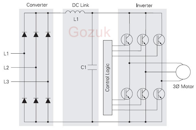
Such a system requires a number of components including line input and VFD output contactors, a bypass DOL starter contactor, thermal overload, timing and logic control and wiring to suit.
Bear in mind that the output terminals of the VFD should not be exposed to mains power during this procedure and also be mindful that until it’s magnetic field collapses a 3 phase induction motor will act as a generator and will deliver an EMF direct to the VFD output terminals on changing back to normal operation if the following logic is not adhered to.
The bypass change over system should be designed such that the VFD is taken out of circuit and the motor run DOL from the suitably rated bypass contactor on the line side of the variable frequency drive.
The output contactor and bypass DOL starter must be electrically and mechanically interlocked to prevent simultaneous closure.
On switching to bypass
The timing logic must ensure time delays in the switching circuit to ensure that on switching to bypass the line contactor opens first followed by the output contactor opening after a delay of 1 to 2 seconds. The bypass DOL starter should then closes after a further delay of 1 to 2 seconds.
On switching to normal
The timing logic must ensure time delays in the switching circuit to ensure that on switching to normal the bypass DOL starter opens first followed by the output contactor closing after a delay of 3 seconds, the line contactor then closes after a further delay of 1 to 2 seconds. The above bypass procedures can be initiated by suitably designed and configured manual process or automatically by a control signal from your management system, supported by adequate documentation and labeling.
-
Was the VFD engineered and designed into the original system to deliver primary process control?
What function does the VFD perform?
-
Is it used as part of a variable air volume (VAV) air conditioning system?
-
Is it used as part of a pump pressure control system?
- If it’s part of a VAV duct pressure control system what happens if you bypass the VFD and deliver a sudden impact rush of full air pressure into a duct system which may have restricted damper conditions, will it rupture or damage the ducting or dampers?
Given in this instance that the VFD was designed into the system from the start, it follows that the fuses or circuit breakers selected for the VFDs low starting current characteristics may not be adequate for conventional DOL starting duty.
In bypass will there be adequate motor thermal protection, previously provided by the VFD?
Bear in mind that the primary process control and or energy saving is lost in bypass situations. OK let’s assume that the VFD was not engineered and designed into the original system but was retrofitted at a later stage and that the existing power cables and original starting arrangements have stayed in place. So in the event of a bypass the original thermal overloads would, subject to appropriate calibration be available to protect the motor.
All well and good but what about the ancillary considerations mentioned above, including the loss of primary process control and or energy savings in bypass.
Is the VFD to be bypassed for maintenance and servicing?
Sometimes with good intent, VFDs are arranged with bypass provisions as part of their design with the intention that routine maintenance and servicing can be carried out to the VFD without loss of mission critical functionality. Great idea but how will the VFD be isolated to allow this to happen?
Ordinary contactors on the input and output of a VFD as part of a bypass system do not normally comply with the AS3000 (Wiring rules) requirements for isolation devices.
If the intent is to allow access to the VFD for maintenance during bypass operation, then appropriate switchgear and proper physical segregation arrangements are mandatory for personal safety. For this reason, designs that involve building the bypass function into the VFD will generally fail to meet this intent. In the event that the VFD requires some extensive repair, necessitating the removal of the VFD to undertake the repair work, it is important that the bypass arrangement can remain in place (requiring separation from the VFD) and active to serve the intended mission critical purpose.
Mission critical bypass
If an item of equipment is truly mission critical then as a first resort have adequate redundancy and backup as part of the design and engineered into the system, for example a run, a stand by and a backup pump all with their respective VFDs.
Where adequate redundancy is impracticable understand the design vulnerabilities and weaknesses of your system and how they will impact upon your business. By all means have a proven bypass strategy in place but understand the impact it will have and ensure sufficient spare parts availability on site and proven processes in place to minimize down time and a return to normal operation.
How to bypass a VFD?
Like most things in life there is more than one way to carry out a variable frequency drive bypass procedure.
Having considered the above and concluded that the electrical supply, circuit breaker or fuses and any other electrical components are adequate for the resultant bypass starting current, that no damage will result to pipe work, seals, ducting, dampers etc, and that removal of the VFD from the controls circuit will not impede the continued satisfactory operation of the controls and most importantly that the bypass operation will achieve the desired result, then you are ready to proceed with the bypass.
The easiest and least complicated way would be to simply have your electrician remove the input and output power cables and connect then in a safe manner external to the VFD. If the VFD is to be removed then all controls connections should also be disconnected. The downside to this is you need a suitably experienced licensed electrician to be available in a timely manner and to have previously determined the suitability of this arrangement to meet your needs.
For mission critical applications where time is of the essence and back up and support staff are not immediately available a fully automated bypass changeover system would be desirable. In this instance all of the above considerations would have been taken into account and the outcome proven to furnish a satisfactory continuance of the mission critical status.
Such a system requires a number of components including line input and VFD output contactors, a bypass DOL starter contactor, thermal overload, timing and logic control and wiring to suit.
Bear in mind that the output terminals of the VFD should not be exposed to mains power during this procedure and also be mindful that until it’s magnetic field collapses a 3 phase induction motor will act as a generator and will deliver an EMF direct to the VFD output terminals on changing back to normal operation if the following logic is not adhered to.
The bypass change over system should be designed such that the VFD is taken out of circuit and the motor run DOL from the suitably rated bypass contactor on the line side of the variable frequency drive.
The output contactor and bypass DOL starter must be electrically and mechanically interlocked to prevent simultaneous closure.
On switching to bypass
The timing logic must ensure time delays in the switching circuit to ensure that on switching to bypass the line contactor opens first followed by the output contactor opening after a delay of 1 to 2 seconds. The bypass DOL starter should then closes after a further delay of 1 to 2 seconds.
On switching to normal
The timing logic must ensure time delays in the switching circuit to ensure that on switching to normal the bypass DOL starter opens first followed by the output contactor closing after a delay of 3 seconds, the line contactor then closes after a further delay of 1 to 2 seconds. The above bypass procedures can be initiated by suitably designed and configured manual process or automatically by a control signal from your management system, supported by adequate documentation and labeling.
Post a Comment:
You may also like:
Featured Articles
Variable frequency drive Rectifier
 To understand variable frequency drive (VFD) better, it's necessary to explain some of the main parts of the variable frequency ...
 To understand variable frequency drive (VFD) better, it's necessary to explain some of the main parts of the variable frequency ...
VFD controlled Induction motor ...
 This paper presents a procedure to measure the efficiency on an induction motor fed by a VFD by the all operation range to speed ...
 This paper presents a procedure to measure the efficiency on an induction motor fed by a VFD by the all operation range to speed ...
VFD: Pulse Width Modulation (PWM)
 Pulse Width Modulation (PWM) VFDs provide a more sinusoidal current output to control frequency and voltage supplied to an AC ...
 Pulse Width Modulation (PWM) VFDs provide a more sinusoidal current output to control frequency and voltage supplied to an AC ...
Variable frequency drive Advantages & ...
VFDs are good for variable speed, in a water pump this is used to maintain a steady pressure, they will smooth out variances in ...
Variable frequency drive Energy saving
 Energy can be saved in a VFD by reducing the losses in the electric motor or by reducing the energy consumption of the variable ...
 Energy can be saved in a VFD by reducing the losses in the electric motor or by reducing the energy consumption of the variable ...
VFD manufacturers
