VFD: Insulated Gate Bipolar Transistor (IGBT)
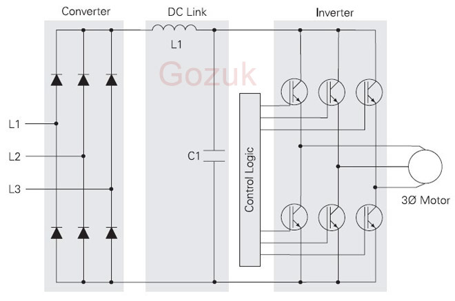
IGBT (insulated gate bipolar transistor) provides a high switching speed necessary for PWM VFD operation. IGBTs are capable of switching on and off several thousand times a second. A VFD IGBT can turn on in less than 400 nanoseconds and off in approximately 500 nanoseconds. A VFD IGBT consists of a gate, collector and an emitter. When a positive voltage (typically +15 VDC) is applied to the gate the IGBT will turn on. This is similar to closing a switch. Current will flow between the collector and emitter. A VFD IGBT is turned off by removing the positive voltage from the gate. During the off state the IGBT gate voltage is normally held at a small negative voltage (-15 VDC) to prevent the device from turning on.

All modern VFDs use power devices known as Insulated Gate Bipolar Transistors (IGBTs). These devices make it possible to minimize annoying audible noise by using switching frequencies beyond the audible range. Unfortunately, VFDs using IGBTs, present a high potential for generating RFI - Radio Frequency Interference. Fast switching in these devices generates sharp-edged waveforms with high frequency components that generate more RFI. The most likely complaint is interference with AM band radios 500-1600 Khz. Nonetheless, sensitive computers, medical equipment and other noise-sensitive devices sharing the same power buss could experience serious interference.
In extreme cases, the VFD itself can experience electrical noise interference (how to reduce the noise?). If elevator machine room equipment is not correctly laid out and properly wired, the electrical noise propagated by the elevator VFD system can interfere with the elevator controller.
An example is the building lacking a solid grounding system where the variable frequency drive system experienced multiple problems. A solid earth ground was provided to eliminate many electrical noise problems, yet the VFD itself was being affected by undetermined sources of noise.
The routing of the contractor's field wiring into the controller was examined and several deficiencies were found and corrected. It was subsequently determined that the step down power/isolation transformer required by this particular application was physically located too close to the front of the controller. With the controller door open, the transformer created interference that affected the control microcomputers. The remedy was placement of a shield between the transformer and the controller, although other methods may have also worked.
WANT TO KNOW HOW IGBT PROTECT THE VFD DRIVES FROM SHORT CIRCUITS .
Post a Comment:
You may also like:
Featured Articles
Variable frequency drive Rectifier
 To understand variable frequency drive (VFD) better, it's necessary to explain some of the main parts of the variable frequency ...
To understand variable frequency drive (VFD) better, it's necessary to explain some of the main parts of the variable frequency ...VFD controlled Induction motor ...
 This paper presents a procedure to measure the efficiency on an induction motor fed by a VFD by the all operation range to speed ...
This paper presents a procedure to measure the efficiency on an induction motor fed by a VFD by the all operation range to speed ...VFD: Pulse Width Modulation (PWM)
 Pulse Width Modulation (PWM) VFDs provide a more sinusoidal current output to control frequency and voltage supplied to an AC ...
Pulse Width Modulation (PWM) VFDs provide a more sinusoidal current output to control frequency and voltage supplied to an AC ...Variable frequency drive Advantages & ...
VFDs are good for variable speed, in a water pump this is used to maintain a steady pressure, they will smooth out variances in ...
Variable frequency drive Energy saving
 Energy can be saved in a VFD by reducing the losses in the electric motor or by reducing the energy consumption of the variable ...
Energy can be saved in a VFD by reducing the losses in the electric motor or by reducing the energy consumption of the variable ...
VFD manufacturers