VFD controlled Induction motor Efficiency measurement
Abstract: This paper presents a procedure to measure the efficiency on an induction motor fed by a VFD by the all operation range to speed and torque. The paper describes the procedure, and accuracy requirements of the instrumentation required by international standards and research results to ensure the measurement of real efficiency of induction motors and VFDs. Also, describes the basic measurement requirements of the variables, accurate data measurement, information processing, power and efficiency calculations. The paper describes and analyzes the different power calculations implemented and researched, which correspond to algorithms used by the commercial instrumentation. The losses on the induction motor–VFD system are shown and analyzed. Finally, the procedure for efficiency measurement is implemented through lab tests.
Nowadays, electrical motors are widely used in industry. This is why they are the main source of energy consumption in the world, with 40% and can be responsible of worldwide 13% CO2 emissions. Within this sector, squirrel-cage induction motor dominates the use of motors in industry, with 90%. Thus, it is important to improve the operation efficiency in the induction motor, because this improves energy consumption and reduces polluting emissions.
To improve productivity and energy saving on induction motor, the use of a VFD (variable frequency drive) has been implemented, as these regulate speed or torque in the motor. However, it must be emphasized that the use of variable frequency drive with motors is viable for large and medium motors, or for applications when we have variable load. Hence, measurement and classification of energy efficiency of the VFD-controlled motor are important to reduce energy consumption and polluting emissions. However, test procedures for appropriate efficiency measurement must be developed to establish such classification, which can be incorporated into a standard or universal procedure, for the usefulness of globalized markets and for industrial clients.
The International Electrotechnical Commission (IEC) sets the 60034-2-3 Standard in order to determine losses and efficiency in alternating current (AC) motors fed by a variable frequency drive. However, the test method is defined for fundamental frequency and rated motor speed. The standard does not characterize all of the losses due to harmonics in the induction motor - variable frequency drive system, and does not detail the steps of the procedure for the measurement of efficiency. Several researchers have worked on the development of methods, models, measuring stations, testing three-phase and double-three phase induction motors, tests with different control signals and instruments for determining the induction motor – variable frequency drive overall efficiency.
This paper presents the procedure to measure efficiency in the system of induction motor - variable frequency drive, and a comparison of methods for efficiency calculations, next to the behavior analysis of the induction motor within its range of operation.
Motor - VFD system losses
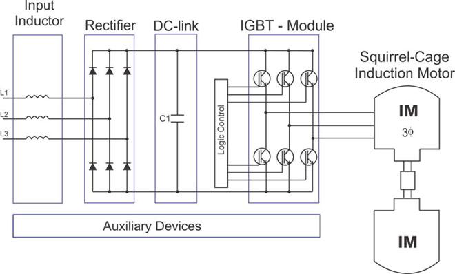
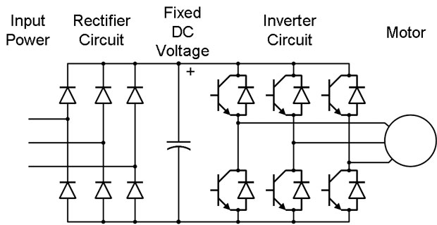
The motor VFD system (induction motor – variable frequency drive system) voltage source inverter (VSI) type is presented in Figure 1. Each module of the system presents different types of mechanical and electrical losses which affect the efficiency of the system and produce undesired effects in the VFD performance. The development and availability of power electronic devices such as FETs, BJTs, IGBTs and GTOs have allowed the commercialization of indirect variable frequency drives by pulse width modulation (PWM) and by consequence to be widely implemented in addition to offer a high performance.
a. VFD (variable frequency drive) losses
The VFD is composed of the following elements, which present different losses:
VFD Inductor losses: The inductor is at the entrance of the variable frequency drive and is implemented as an AC harmonic filter. This VFD element has power losses in the core and windings. The most used model to determine the losses is by a resistive-inductive impedance in series as shown in equation (1).
VFD Diode bridge losses: Losses in the VFD diode bridge can be represented as a function of small leaks that occur in the diode when this works in direct or inverse polarization. Equation (2) models these losses.
VFD DC Bus losses: VFDs have a DC bus capacitor to avoid the ripple in the signal. Because of the VFD DC bus interconnects the diode bridge with IGBT bridge; the current will be the sum of a DC component and the harmonics produced by the bridge rectifier and the inverter bridge. Therefore, the VFD DC voltage produced by the rectifier has a large number of harmonics. Equation (3) represents the losses in the capacitor.
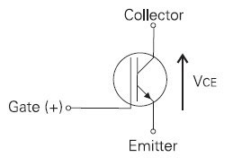
VFD IGBT module losses: The losses in the IGBT module can be divided between conduction losses and switching losses. Furthermore, there are additional losses by the diode that generally accompanies the VFD IGBT in parallel. Both for the IGBT and for the diode, the instant conduction losses are expressed in the equation (4) and (5).
VFD Auxiliary devices Losses: The losses that are presented in this VFD controller module are constant and do not significantly affect the induction motor and variable frequency drive overall efficiency. Items that present losses are the micro variable speed controller, the VFD display, the communication bus, the control system, VFD control panel.
b. Squirrel-Cage Induction Motor
The losses in the induction motor due to supply and control of the variable frequency drive are evaluated at steady state. Their losses mainly increase in the iron and on the stator and rotor windings due to voltage and current harmonics. Currently there is no a circuit model to determine the motor losses due to the different frequency spectrums of the current and voltage generated by the variable frequency drive. The IEC 610034-17 Standard states that "There is no a simple method to calculate the additional losses and cannot be established any general rule about its value. Its dependency in relation to different physical characteristics is extremely complex, also exists a large variety of VFDs both as motors and the quality of manufacture of the core is an important feature. "In the IEC 60034-31 standard is commented the determination of motor efficiency fed by the VFD from the IEC 60034-2-3 where according to the European Committee for Electrotechnical Standardization this last will be distributed by November 2012 according to the Committee Draft for VOTE (CDV) established at 2011-10-14.
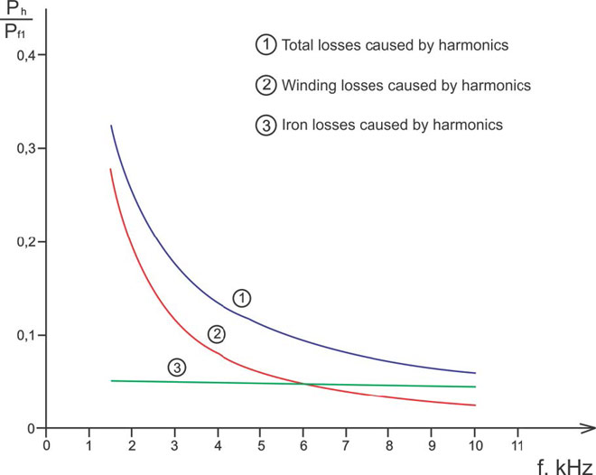
The losses in the induction motor fed by a current VFD in the iron are essentially the same but the losses in the stator and rotor can significantly increase the product of the IGBT switching. In the case of induction motor fed by voltage VFD additional losses in the iron cannot be ignored, losses in the windings are limited by the dispersion reactance and there are no switching losses, due to the switching currents do not flow through the motor windings. The IEC 610034-17 Standard verifies through testing the total value of the additional losses caused by harmonics and note that is not dependent on the load. These losses are reduced when the switching frequency increases as illustrated in Figure 2.
In the procedure for determining experimentally the motor efficiency, the instruments and its accuracy are important. The IEC 60034-2-3 Standard establishes an instrument bandwidth from 5 Hz up to 10 times the switching frequency of the VFD. The requirements of the measurement instruments are defined by the IEEE 112 and IEC 60034-2-1.
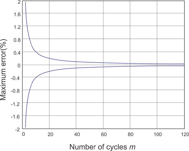
The previous requirements consider the current and voltage harmonics generated by variable frequency drive. Furthermore the signals may contain components or inter-harmonic sub-harmonic signal modifying periodic [16] and can increase the measurement error. The maximum error of measurement is lowered if the number of cycles of the inter-harmonic measured increases, for example contemplating cycles 20 at the measurement it would represent a ±0.2 % error as shown in Figure 3.
The current electric power measurement devices show an increase at the measurement error due to the existence of the high harmonic content of the VFD voltage and current signals further by the lack of synchronization between the fundamental frequency and the sampling frequency. The wattmeters are mainly classified as Regularly Asynchronous Sampling Digital Wattmeter (RASDW) and Regularly Spaced Sampling Digital Wattmeter. The RSSDW present advantages as they are devices easier to implement, low cost and low risk of failure, however they have low bandwidth. The RASDW have good accuracy and a wide bandwidth, however are difficult to implement and require complex and costly measuring instruments. The implementation of the device is mainly characterized by the degree of precision and the types of the algorithms architecture of the meter.
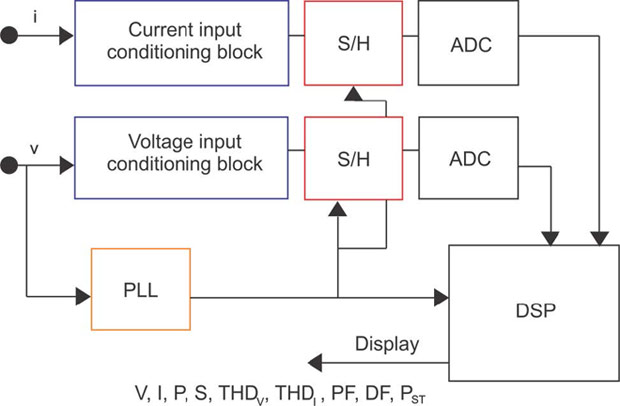
The current architecture of the modern power meter is shown in Figure 4 where the Sample & Hold (S/H) and Phase-Locked Loop (PLL) blocks are responsible for a correct and accurate sampling. The Digital Signal Processing (DSP) handles the computation of the respective acquired signals and it's computing through different algorithms to calculate voltage, current, power, among others. The Analog-to-Digital Converter (ADC) and the voltage and current conditioning blocks to attenuate or amplify the input signals.
Calculation methods of electric power
The three calculation methods of power developed below are used to determine the efficiency of the squirrel-cage motor induction and variable frequency drive.
a. Fourier decomposition method
The Fourier series are used widely to describe non-sinusoidal periodic waveforms in terms of a sinusoidal series. The power relations for electrical and electronic circuits with non-sinusoidal periodic voltages and / or currents can be expressed in terms of the components of the Fourier series. The Fourier series can express a periodic function f(t) as trigonometric, as presented in equation (8) and (9).
This power calculation method is based on the analysis of voltages and currents in the discrete domain. Because of the voltage and current signals are sampled over time and stored in digital records. In applying the laws of electrical circuits is obtained the expression of equation (15) for the time domain and for a number N discrete samples:
This method is based on Parks transformation that represents the three-phase system in a new reference framework whose components are the direct axis component, quadrature and zero sequence. Considering the three-phase voltage and current signals, the Parks transformation Equation (16) must be applied to make the change of reference and the calculation of power in Equation (17).
Analysis of Results
Some results obtained from testing according to efficiency measurement procedure. The figure shows the software developed for the determination of overall efficiency induction motor - variable frequency drive. The program allows visualizing voltage and current signals, harmonic magnitude of each signal, harmonic angles of each signal in respect with its fundamental component and system efficiency for different load values. In addition, the program calculates power using the three methods outlined above. It is noted that for the experimental test at 1800 rpm (input frequency: 60 Hz), the efficiency calculated under the three power methods is similar. The measurement instruments that are used for the power calculation by the VI method, do not present major problems for data obtaining. However, when the testing is made in other frequency ranges powers methods deliver different results, because the methods include the harmonics that are present in the electrical signals of the variable frequency drive system.
Although the power calculation method based on the decomposition of the signal by Fourier takes into account the different harmonics that may occur in the voltage and current signals of periodic non-sinusoidal waves, this method presents higher efficiency values at low operation speed. The orthogonal method presents greater capacity for calculating the efficiency within the operating range for the motor speed.
Conclusions
The results point that the algorithm implemented in the instrument to take no lower than 40 cycles of samples in order to obtain a 0.1% error in the power calculation. This demonstrates the influence of the inter-harmonics in the power calculation by the instrument and is recommended to increase the number of sampling cycles. The measurement instrument used to test the procedure took only 4 cycles of samples, where the figure 3 indicated that the maximum error in the measurement is ±1%. The results have been illustrated by means of simple examples.
The proposed procedure for determining the efficiency of the squirrel cage induction motor powered by a VFD allows obtaining the efficiency curves of all the equipment under test and the overall system in a simple and practical way, in order to make a future efficiency rating of the whole induction motor - variable frequency drive.
The results of the measurement can be affected by the instrument uncertainty and error. On one hand, the instrument uncertainty is related with external sources such as noises and test numbers. While the error, is concerned with the instrument characteristics. Most of the measurement instruments use the "Regulary spaced sampling digital wattmeter" which implements a PLL (Phase Locked Loop) block. This subsystem does not take the exactly multiple frequency of the fundamental signal. Therefore, the significant values of the different power calculation methods will be affected. In order to reduce this error, we suggest a Random asynchronus sampling digital wattmeter.
The efficiency determination methods are under investigation to identify the relationship of the harmonics, PWM, variable speed losses over the final efficiency the whole induction motor - variable frequency drive.
Nowadays, electrical motors are widely used in industry. This is why they are the main source of energy consumption in the world, with 40% and can be responsible of worldwide 13% CO2 emissions. Within this sector, squirrel-cage induction motor dominates the use of motors in industry, with 90%. Thus, it is important to improve the operation efficiency in the induction motor, because this improves energy consumption and reduces polluting emissions.
To improve productivity and energy saving on induction motor, the use of a VFD (variable frequency drive) has been implemented, as these regulate speed or torque in the motor. However, it must be emphasized that the use of variable frequency drive with motors is viable for large and medium motors, or for applications when we have variable load. Hence, measurement and classification of energy efficiency of the VFD-controlled motor are important to reduce energy consumption and polluting emissions. However, test procedures for appropriate efficiency measurement must be developed to establish such classification, which can be incorporated into a standard or universal procedure, for the usefulness of globalized markets and for industrial clients.
The International Electrotechnical Commission (IEC) sets the 60034-2-3 Standard in order to determine losses and efficiency in alternating current (AC) motors fed by a variable frequency drive. However, the test method is defined for fundamental frequency and rated motor speed. The standard does not characterize all of the losses due to harmonics in the induction motor - variable frequency drive system, and does not detail the steps of the procedure for the measurement of efficiency. Several researchers have worked on the development of methods, models, measuring stations, testing three-phase and double-three phase induction motors, tests with different control signals and instruments for determining the induction motor – variable frequency drive overall efficiency.
This paper presents the procedure to measure efficiency in the system of induction motor - variable frequency drive, and a comparison of methods for efficiency calculations, next to the behavior analysis of the induction motor within its range of operation.
Motor - VFD system losses
The motor VFD system (induction motor – variable frequency drive system) voltage source inverter (VSI) type is presented in Figure 1. Each module of the system presents different types of mechanical and electrical losses which affect the efficiency of the system and produce undesired effects in the VFD performance. The development and availability of power electronic devices such as FETs, BJTs, IGBTs and GTOs have allowed the commercialization of indirect variable frequency drives by pulse width modulation (PWM) and by consequence to be widely implemented in addition to offer a high performance.

a. VFD (variable frequency drive) losses
The VFD is composed of the following elements, which present different losses:
VFD Inductor losses: The inductor is at the entrance of the variable frequency drive and is implemented as an AC harmonic filter. This VFD element has power losses in the core and windings. The most used model to determine the losses is by a resistive-inductive impedance in series as shown in equation (1).
1) Pchoke(t) = 3i2L(t)ESRLWhere iL is the instantaneous current line of the inductor, ESRL is the equivalent series resistance. ESRL is calculated from the current measurements and losses at the entrance.
VFD Diode bridge losses: Losses in the VFD diode bridge can be represented as a function of small leaks that occur in the diode when this works in direct or inverse polarization. Equation (2) models these losses.
2) Pdiode,on(t) = UFidiode(t) + RFi2diode(t)Where idiode(t) is the instantaneous current that flows through the diode, UF is the voltage drop when diode is forward biased while RF is the internal diode resistance.
VFD DC Bus losses: VFDs have a DC bus capacitor to avoid the ripple in the signal. Because of the VFD DC bus interconnects the diode bridge with IGBT bridge; the current will be the sum of a DC component and the harmonics produced by the bridge rectifier and the inverter bridge. Therefore, the VFD DC voltage produced by the rectifier has a large number of harmonics. Equation (3) represents the losses in the capacitor.
3)Where IC(n) is the RMS value of the capacitors nth order current and ESRC(n) is the equivalent series resistance of the capacitor for a particular frequency.
VFD IGBT module losses: The losses in the IGBT module can be divided between conduction losses and switching losses. Furthermore, there are additional losses by the diode that generally accompanies the VFD IGBT in parallel. Both for the IGBT and for the diode, the instant conduction losses are expressed in the equation (4) and (5).
4)Where im is the phase current of the induction motor, UCE0 is the threshold voltage of the VFD IGBT, RCE0 is the resistance of the IGBT turn-on mode. Moreover, the variables for the diode losses correspond to the diode voltage and the internal resistance of the element (UF0 and RF0 respectively). The losses in the VFD IGBT and in the diode due to switching can be expressed by equation (6) and (7).
5)
6)Where Nsw,change is the number of switches in a specific period of time, Esw is the switching energy losses in the respective element, UDC and Im are switching voltages and currents.
7)
VFD Auxiliary devices Losses: The losses that are presented in this VFD controller module are constant and do not significantly affect the induction motor and variable frequency drive overall efficiency. Items that present losses are the micro variable speed controller, the VFD display, the communication bus, the control system, VFD control panel.
b. Squirrel-Cage Induction Motor
The losses in the induction motor due to supply and control of the variable frequency drive are evaluated at steady state. Their losses mainly increase in the iron and on the stator and rotor windings due to voltage and current harmonics. Currently there is no a circuit model to determine the motor losses due to the different frequency spectrums of the current and voltage generated by the variable frequency drive. The IEC 610034-17 Standard states that "There is no a simple method to calculate the additional losses and cannot be established any general rule about its value. Its dependency in relation to different physical characteristics is extremely complex, also exists a large variety of VFDs both as motors and the quality of manufacture of the core is an important feature. "In the IEC 60034-31 standard is commented the determination of motor efficiency fed by the VFD from the IEC 60034-2-3 where according to the European Committee for Electrotechnical Standardization this last will be distributed by November 2012 according to the Committee Draft for VOTE (CDV) established at 2011-10-14.
The losses in the induction motor fed by a current VFD in the iron are essentially the same but the losses in the stator and rotor can significantly increase the product of the IGBT switching. In the case of induction motor fed by voltage VFD additional losses in the iron cannot be ignored, losses in the windings are limited by the dispersion reactance and there are no switching losses, due to the switching currents do not flow through the motor windings. The IEC 610034-17 Standard verifies through testing the total value of the additional losses caused by harmonics and note that is not dependent on the load. These losses are reduced when the switching frequency increases as illustrated in Figure 2.

In the procedure for determining experimentally the motor efficiency, the instruments and its accuracy are important. The IEC 60034-2-3 Standard establishes an instrument bandwidth from 5 Hz up to 10 times the switching frequency of the VFD. The requirements of the measurement instruments are defined by the IEEE 112 and IEC 60034-2-1.
The previous requirements consider the current and voltage harmonics generated by variable frequency drive. Furthermore the signals may contain components or inter-harmonic sub-harmonic signal modifying periodic [16] and can increase the measurement error. The maximum error of measurement is lowered if the number of cycles of the inter-harmonic measured increases, for example contemplating cycles 20 at the measurement it would represent a ±0.2 % error as shown in Figure 3.

The current electric power measurement devices show an increase at the measurement error due to the existence of the high harmonic content of the VFD voltage and current signals further by the lack of synchronization between the fundamental frequency and the sampling frequency. The wattmeters are mainly classified as Regularly Asynchronous Sampling Digital Wattmeter (RASDW) and Regularly Spaced Sampling Digital Wattmeter. The RSSDW present advantages as they are devices easier to implement, low cost and low risk of failure, however they have low bandwidth. The RASDW have good accuracy and a wide bandwidth, however are difficult to implement and require complex and costly measuring instruments. The implementation of the device is mainly characterized by the degree of precision and the types of the algorithms architecture of the meter.
The current architecture of the modern power meter is shown in Figure 4 where the Sample & Hold (S/H) and Phase-Locked Loop (PLL) blocks are responsible for a correct and accurate sampling. The Digital Signal Processing (DSP) handles the computation of the respective acquired signals and it's computing through different algorithms to calculate voltage, current, power, among others. The Analog-to-Digital Converter (ADC) and the voltage and current conditioning blocks to attenuate or amplify the input signals.

Calculation methods of electric power
The three calculation methods of power developed below are used to determine the efficiency of the squirrel-cage motor induction and variable frequency drive.
a. Fourier decomposition method
The Fourier series are used widely to describe non-sinusoidal periodic waveforms in terms of a sinusoidal series. The power relations for electrical and electronic circuits with non-sinusoidal periodic voltages and / or currents can be expressed in terms of the components of the Fourier series. The Fourier series can express a periodic function f(t) as trigonometric, as presented in equation (8) and (9).
8)Alternatively, equations (10) and (11) combine an and bn factors into a single sinusoid.
9)
10)The term a0 is a constant, which corresponds to the root mean square (RMS) value of f(t), and represents a voltage or current (DC). Furthermore, the coefficient C1 is the amplitude of the fundamental frequency term ω_0, while the coefficients C2, C3... are the amplitudes of the harmonics. The RMS value can be calculated by the equation (12).
11)
12)Finally, based on the periodic waveform of voltage and current represented by the Fourier series, the electric power is calculated by the equation (13).
13)The electric power for non-sinusoidal periodic voltage and current waveforms is calculated by the equation (14):
14)b. VI Power calculation method
This power calculation method is based on the analysis of voltages and currents in the discrete domain. Because of the voltage and current signals are sampled over time and stored in digital records. In applying the laws of electrical circuits is obtained the expression of equation (15) for the time domain and for a number N discrete samples:
15)c. Orthogonal Method
This method is based on Parks transformation that represents the three-phase system in a new reference framework whose components are the direct axis component, quadrature and zero sequence. Considering the three-phase voltage and current signals, the Parks transformation Equation (16) must be applied to make the change of reference and the calculation of power in Equation (17).
16)Where the 3/2 factor depends on the matrix used for transformation. This change of reference framework is commonly used in the analysis of AC machines, as in the measurement of components of the power systems and some control systems associated with electrical systems.
17)
Analysis of Results
Some results obtained from testing according to efficiency measurement procedure. The figure shows the software developed for the determination of overall efficiency induction motor - variable frequency drive. The program allows visualizing voltage and current signals, harmonic magnitude of each signal, harmonic angles of each signal in respect with its fundamental component and system efficiency for different load values. In addition, the program calculates power using the three methods outlined above. It is noted that for the experimental test at 1800 rpm (input frequency: 60 Hz), the efficiency calculated under the three power methods is similar. The measurement instruments that are used for the power calculation by the VI method, do not present major problems for data obtaining. However, when the testing is made in other frequency ranges powers methods deliver different results, because the methods include the harmonics that are present in the electrical signals of the variable frequency drive system.
Although the power calculation method based on the decomposition of the signal by Fourier takes into account the different harmonics that may occur in the voltage and current signals of periodic non-sinusoidal waves, this method presents higher efficiency values at low operation speed. The orthogonal method presents greater capacity for calculating the efficiency within the operating range for the motor speed.
Conclusions
The results point that the algorithm implemented in the instrument to take no lower than 40 cycles of samples in order to obtain a 0.1% error in the power calculation. This demonstrates the influence of the inter-harmonics in the power calculation by the instrument and is recommended to increase the number of sampling cycles. The measurement instrument used to test the procedure took only 4 cycles of samples, where the figure 3 indicated that the maximum error in the measurement is ±1%. The results have been illustrated by means of simple examples.
The proposed procedure for determining the efficiency of the squirrel cage induction motor powered by a VFD allows obtaining the efficiency curves of all the equipment under test and the overall system in a simple and practical way, in order to make a future efficiency rating of the whole induction motor - variable frequency drive.
The results of the measurement can be affected by the instrument uncertainty and error. On one hand, the instrument uncertainty is related with external sources such as noises and test numbers. While the error, is concerned with the instrument characteristics. Most of the measurement instruments use the "Regulary spaced sampling digital wattmeter" which implements a PLL (Phase Locked Loop) block. This subsystem does not take the exactly multiple frequency of the fundamental signal. Therefore, the significant values of the different power calculation methods will be affected. In order to reduce this error, we suggest a Random asynchronus sampling digital wattmeter.
The efficiency determination methods are under investigation to identify the relationship of the harmonics, PWM, variable speed losses over the final efficiency the whole induction motor - variable frequency drive.
Post a Comment:
You may also like:
Featured Articles
What is VFD, How it works? - VFD ...
 VFD is shorted for Variable Frequency Drive (also known as AC Drives and Inverters) -- that's used to make an AC motor working in ...
 VFD is shorted for Variable Frequency Drive (also known as AC Drives and Inverters) -- that's used to make an AC motor working in ...
VFD: Insulated Gate Bipolar Transistor ...
 IGBT (insulated gate bipolar transistor) provides a high switching speed necessary for PWM VFD operation. IGBTs are capable of ...
 IGBT (insulated gate bipolar transistor) provides a high switching speed necessary for PWM VFD operation. IGBTs are capable of ...
Three phase inverters
 In the variable frequency drive rectifier paper, it explains how to go from three phase alternating current voltage to a direct ...
 In the variable frequency drive rectifier paper, it explains how to go from three phase alternating current voltage to a direct ...
Variable Frequency Drive Harmonics and ...
A discussion of the benefits of variable frequency drives often leads to a question regarding electrical harmonic distortion ...
Variable frequency drive Rectifier
 To understand variable frequency drive (VFD) better, it's necessary to explain some of the main parts of the variable frequency ...
 To understand variable frequency drive (VFD) better, it's necessary to explain some of the main parts of the variable frequency ...
VFD manufacturers


