Home » Case study » Static head of submersible sewage pump
Static head of submersible sewage pump
Case: How to calculate the static head of submersible sewage pump? Is it the elevation difference between water level in the sump and the discharge at top of the sump? Or it is the elevation difference between the water level in the sump and the highest point at the pipe line? Or it is something else?
I have a case where the pump is at 10m from seal level, water level is at 12m, sump height 18m, highest point at the pipe line is at 25m, and discharge of pipe line is at 5m.
A:
In general...
Pump Head Required = "Lift Required " (feet) + Dynamic Head loss (feet at GPM) + Discharge Pressure (feet)
Lift Required = Discharge Level Height - Initial Water Level Height
Dynamic Head loss = the sum of all piping, fittings, and fixtures between the pump and atmosphere.
Discharge Pressure = Required PSI x 2.31 = feet
This will give you required pump head at GPM.
Note that Discharge Pressure (ft) must be greater than the difference between pump max lift (to highest point) and discharge level (to initially charge the pipe to the highest point before you can benefit from the fall to give head gain).
The worst case static head (to overcome) is from the lowest source water level to the highest level of lift required (as Terry mentioned) at start-up.
Static Head (idle) = Lowest level of pump suction - Highest point in pipeline = 10m - 25m = - 15m. (You need to supply 15 m of head gain to overcome initial static head.)
But if I'm visualizing the application correctly from your description, after the static head is overcome and flow is started, you have a syphon.
IE, once flow at discharge is started, you will have a static head (gain).
Static Head (syphon) = Source water level - syphon discharge level.
For the case of current water level...
12m - 5 m = 7m static head gain
For min sump level 10m - 5 m = 5 m
and for max sump level 18 m - 5 m = 13 m.
You need to take this into account for your pump sizing.
If the pump head required to get design flow (with the benefit of the syphon head gain) is greater than the initial static lift required, you don't have to worry about it.
However, you should not assume that a siphon will be present after pump start because this may not be the case. The presence of a siphon will depend on what type of air release valves or anti-siphon valves exist in the system, where they are located and whether the Hydraulic Grade Line for the system is above or below those valves. The absence of an anti-siphon valve does not guarantee a siphon either.
Furthermore, the system may transition between siphon and non-siphon conditions, particularly if the flow range is large. This could be a result of using multiple duty pumps and/or variable frequency drives.
If this is an existing system and you're having problems, there's a high probably that the static head hasn't been properly addressed during design. You may have unstable duty conditions and the pumps may operate anywhere from too far left of curve to too far right of curve. If the pipeline undulates and the HGL is close to pipe level, air may enter the pipeline at air release valves and create increased static head due to air pockets in the pipework.
If you're designing this system, it's generally best to design so that it works with either siphon all the time or no siphon at all. Try to keep the HGL well above undulating pipes to avoid entry of air into the pipe. Make sure you check for all combinations of pumps operating, all operating speeds and check maximum and minimum system resistance curves.
If transition between siphon and non-siphon is unavoidable, be very careful with pump selections and control philosophy. Aim to operate vfd pumps in the acceptable operating range (typically 65% to 115% of Best Efficiency Point flow) where run-time is significant (e.g. more than 100 hours/year depending on severity). You may need to shut down a pump once siphon is established. Also, move through the siphon/non-siphon transition region reasonably quickly so as to ensure the system remains stable otherwise surging may result (especially in large, long systems).
Post a Comment:
You may also like:
Featured Articles
VFD for pumps in variable flow water ...
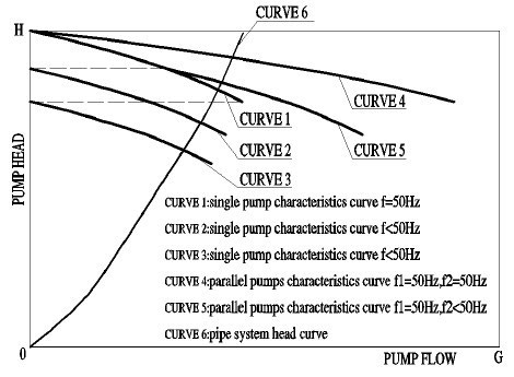 Variable flow water system has played an important role in the field of energy saving with the VFD widely used in practical ...
Variable flow water system has played an important role in the field of energy saving with the VFD widely used in practical ...VFD in China plantation irrigation ...
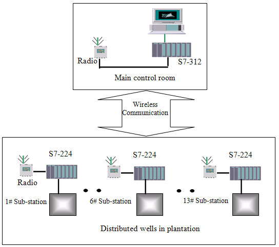 This article have a study of the wireless group control system with variable frequency drive (VFD) applied in a Chinese ...
This article have a study of the wireless group control system with variable frequency drive (VFD) applied in a Chinese ...Variable frequency drive energy ...
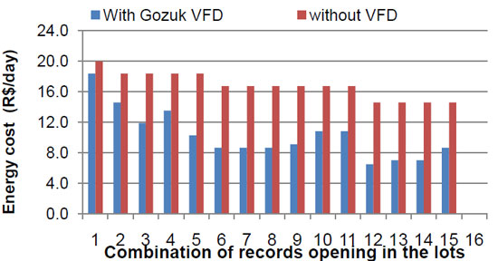 Notes that for the combinations where we had the same number of opened records, the power suffers no change, but when it is used ...
Notes that for the combinations where we had the same number of opened records, the power suffers no change, but when it is used ...Variable frequency drive on Cooling ...
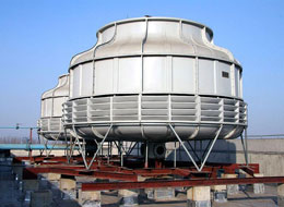 We are working on a study related to Cooling Towers. We want to decrease cooling water supply temperature going to steam ...
We are working on a study related to Cooling Towers. We want to decrease cooling water supply temperature going to steam ...
VFD manufacturers