Home » Case study » VFD for pumps in variable flow water system
VFD for pumps in variable flow water system
Variable flow water system has played an important role in the field of energy saving with the VFD widely used in practical projects. How to control the VFD to work properly is an essential issue which we must first emphatically solve. The control technology of VFD is closely related to characteristics of pumps. Based on the mathematical a model of pumps with or without variable frequency drives, the paper discusses some issues in detail, such as variable frequency drives configuration, flow rate regulation and overload. These are key issues of control technology of variable flow water system. For those multiple-pump water systems, the engineers may select synchronous frequency conversion control technology or Add-Sub pumps control technology to achieve the maximum energy saving benefits.
Introduction
In recent years, the heating and air conditioning water system began using variable flow technology. Circulation pump motors are driven by variable frequency drives to reduce energy consumption, and the advantages that the variable flow technology brings is obvious.
Numerous studies conducted by many researchers have identified significant energy savings potential by regulating flow rates to meet process demands. But, characteristics of pumps with VFD technology are quite different from those of pumps without variable frequency drives, and pumps in parallel of multiple-pumps system would make this situation more complex. In other way there are still many issues worth discussing, for example, how to configure variable frequency drives for water pumps, how to change system flow correctly, and how to avoid pumps overload? This paper will address these issues based on the pump models.
Mathmatical Model of Pump
1. Model of Pump without Variable frequency drive
The basic parameters of water pump include the pump flow and pump head. Under normal conditions we can use the pump characteristics curve to express the model of water pump. The Figure 1 sketches the relationship between pump head with pump flow, the single pump characteristics curve is illustrated with curve 1 and the curve 2 illustrates two parallel pumps characteristics curve in Figure 1. The curve 3 in Figure1 illustrates the pipe system head curve.
The water pump union operating point is point A under designed operating condition, and operating point of the single pump is point C, Figure 1 below sketches these relationships. When the two pumps all put in operation, the total flow is 2Q0 (Q0 is rated flow of single pump) and flow rate provided by each pump is Q0. We can also use formula to express mathematical model without variable frequency drive of water pump:
2. Model of Pump with Variable frequency drive
In order to realize the variable flow technology, the water pump motors are actuated by the variable frequency drives. For this reason the mathematical model of the pump with new features would be more complicated.
Similar to the Figure 1, the single pump characteristics curve is illustrated with curve 1 and the curve 2 illustrates two parallel pumps characteristics curve in Figure 2, and the pumps operate under the power frequency. According to the pump law of hydraulic similarity, we can get the different pump characteristics curves under different frequency, and the formula (3) below illustrates the pump law of hydraulic similarity.
In Figure 2, curve 4 can be derived based on curve 1 and the curve 5 can be derived based on curve 2. The curve 4 illustrates single pump characteristics curve, the curve 5 illustrates parallel pump characteristics curve, which operating frequencies are all 25Hz controlled by VFD.
Analysis of Pump Overload
1. Pipe System Head Curve
Pump overload is a common fault, which could be caused by many reasons. The unreasonable design and unreasonable operation regulation is the main cause. Prior to the further study of the issue, we learn about the pipe system characteristics. Usually we use formula (4) below illustrates pipe system model:
2. Analysis of Pump Overload
As mentioned above, one of the main cause that cause pump overload is unreasonable operation regulation, the heating or air conditioning water system adopt variable flow technology. The flow rate needs to be regulated by changing numbers of operating pumps or pump operating frequency when the building heating or cooling load changes, especially for those multiple-pumps system.
Takes the Figure 2 above (pump with VFD) as our discussion objects, the rated flow of water system is 2Q0 under designed operating condition when two parallel pumps are all put in operation. The union operating point of two parallel pumps is point A and single operating point of each pump is point C, obviously each pump runs normally with its rated flow Q0. The point B is operating point of single pump when only one pump is put in operation. The Figure 2 shows that the water pump actual flow is much greater than its rated flow, pump had been overloaded. The pump head exceeds the pipeline system resistance when system flow reduces, and this is the basic reason that causes pump overload.
Control Technology of Variable Flow Water system
1. Variable frequency drive Configuration
For single pump system the configuration of variable frequency drive is simple, one VFDs only one pump motor. But for multiple pump system how to configure the variable frequency drives? Which method is correct choice, one VFDs one pump motor or one VFDs more pump motors? The correct method is that one VFDs one pump motor, so the number of pumps is equal to the number of variable frequency drives. The Figure 3 below shows this principle. In Figure 3 curve 1, 2, and 3 is single pump characteristics curve at different frequency. There are three different situations for water pumps operating at different frequency in parallel. The curve 4 is the union operating characteristics curve of two pumps which operates at the same frequency, and this is an ideal complete parallel mode. Now we decrease frequency of one pump to lower frequency which corresponds to curve 2. The union operating characteristics curve of two pumps which operates at different frequency changes to curve 5, and this is a partial parallel mode. If continue decrease frequency to frequency the value which corresponds to curve 3, we can see the two pumps could not operating in parallel, the pump operating in lower frequency would not work effectively. So it may be unreasonable that one VFDs more pumps motors.

Fig. 3 VFD configuration
2. Synchronization Frequency Conversion Technology
Now we can assume that the flow rate of the system requirement is changed to 50% of the rated flow, how can we achieve this goal? The easiest method is to use the synchronous frequency conversion technology, that all pumps running at the same frequency. As shown in Figure 2, the operation frequency of all pumps is reduced to 25 Hz by variable frequency drive and parallel pumps characteristics changes from curve 2 to curve 5, at the same time the union operating point of the parallel pumps changes from point A to point B. All the pumps in parallel by simultaneously changing the operation frequency, just like one pump.
3. Anti-overload Technology
Synchronous variable frequency drive converter is a good technology to meet the needs of the water system with variable flow; it also can effectively avoid the water pump and variable frequency drive overload. This technique is suitable for the water system with the small number of pumps. However, when the water system with large number of pumps needs smaller flow, Add-Sub pumps control technology is a better choice. Then it is a viable technology to change the number of running pumps, but this approach applied inappropriately would lead to water pumps and variable frequency drives overload. How can we avoid this? Let us take Figure 4 as an example to analyze.

Fig. 4 Pump Overload Analysis
Now we can assume that the flow rate of the system requirement is changed to 50% of the rated flow, how can we achieve this goal? The easiest method is to use the synchronous frequency conversion technology, that all pumps running at the same frequency. As shown in Figure 2, the operation frequency of all pumps is reduced to 25 Hz by VFD and parallel pumps characteristics changes from curve 2 to curve 5, at the same time the union operating point of the parallel pumps changes from point A to point B. All the pumps in parallel by simultaneously changing the operation frequency, just like one pump.
In Figure 4, the single pump characteristics curve is illustrated with curve 1 and the pump running at the power frequency. The curve 2 illustrates two parallel pumps characteristics curve and all the two parallel pumps running at the power frequency also. The curve 3 illustrates the pipe system head curve. We still assume that the flow rate of the water system requirement is changed to 50% of the rated flow. First of all, what would happen when only one pump is put into operation? A pump operating point is point B and the water pump actual flow is much greater than its rated flow, the pump and variable frequency drive overload or even stop working. We can change single pump characteristics curve from curve 1 to curve 4 by changing the operating frequency, and then pump operating point changes from point B to point D. The pump actual flow rate is just equal to its rated flow, which can be clearly seen from Figure 4. Now the remaining question is how to solve the frequency value corresponds to the curve 4. The following example illustrates the calculation method.
Table 1 below shows the pump parameters, the left data is percent of rated flow (%) and the right data is pump head ( KPa ).
Table 1. Performance Parameters of Pump
Pump performance can be expressed with the formula (1) above, all the coefficient A,B,C can be calculated by curve fitting of the data in the table. The calculated result is A = 380 B = -0.2619 and C = -0.00238 . Then the complete formula to express the pump characteristics list as below:
Variable f1 is operating frequency corresponds to the curve 1 and Variable f4 is operating frequency corresponds to the curve 4. So according to the pump law of hydraulic similarity, we can get:
4. Variable Flow Controller
Author developed an intelligent controller based on single board computer as shown in Figure 5 below, which adopts variable flow technology. The VFD main includes CPU module, real-time clock, analog-to-digital converter (ADC), digital-to-analog converter (DAC), digital-input module with optical isolation, digital-output with optical isolation, and RS232 & RS485 communication module. The VFD completes data acquisition through the digital input and analog-input channels and carries on the analysis to the data, then control the pumps and VFDs to work correctly through the digital-output and analog-output channels.

Fig. 5 Controller for Variable Flow Technology
The dedicated control algorithms and control strategies for variable flow water systems are developed for the VFD. The control algorithms include normal PID control algorithm and fuzzy control algorithm for different control purpose. Practice has proved that fuzzy algorithm is more reasonable than the PID algorithm for most variable flow control. The dedicated control strategies include synchronous frequency conversion technology, Add-Sub pumps control technology and anti-overload technology. Many projects have achieved obvious economic results at minimum costs.
Conclusion
Pumps are the most common engineering facilities in the field of building, but we still need to figure out how to make them work correctly. Most importantly, variable frequency drives have come into wide use nowadays with the development of variable flow technology. Combined application of variable frequency drives and water pumps brings us not only good energy-saving benefits but some new problems, such as variable frequency drives configuration and overload etc. This paper has presented a theoretical study to solve the problems.
To understand the characteristics of the pump, establishment of mathematical model of water pump is the premise. Formula (1) and formula (2) illustrate the pump performance and they are basic equations for pump without inverts. We can derive mathematical model of water pump with variable frequency drive by combining the basic formula with the pump law of hydraulic similarity.
For those multiple-pump systems, it is clear that the number of variable frequency drives should be equal to the number of pumps. This is determined by the characteristics of pumps in parallel. Synchronous frequency conversion technology may be a good choice for water system with smaller number of pumps.
The paper also discussed the issues related to overload. From the discussion, one may conclude that the most important reason which causes overload is pump head exceeds the pipeline system requirement. For those multiple-pump systems, this problem occurs often when only a fraction of pumps are put into operation. Variable frequency technology is a valid method of overcoming overload. Method of calculating operating frequency is more complex and the article illustrates calculation method with an example. This method needs not only the mathematical formulas but also actual performance parameters of pump.
For projects application, choose a suitable VFD is necessary. The VFD with the dedicated control algorithms and control strategies for variable flow technology can solve all those issues discussed above.
Introduction
In recent years, the heating and air conditioning water system began using variable flow technology. Circulation pump motors are driven by variable frequency drives to reduce energy consumption, and the advantages that the variable flow technology brings is obvious.
Numerous studies conducted by many researchers have identified significant energy savings potential by regulating flow rates to meet process demands. But, characteristics of pumps with VFD technology are quite different from those of pumps without variable frequency drives, and pumps in parallel of multiple-pumps system would make this situation more complex. In other way there are still many issues worth discussing, for example, how to configure variable frequency drives for water pumps, how to change system flow correctly, and how to avoid pumps overload? This paper will address these issues based on the pump models.
Mathmatical Model of Pump
1. Model of Pump without Variable frequency drive
The basic parameters of water pump include the pump flow and pump head. Under normal conditions we can use the pump characteristics curve to express the model of water pump. The Figure 1 sketches the relationship between pump head with pump flow, the single pump characteristics curve is illustrated with curve 1 and the curve 2 illustrates two parallel pumps characteristics curve in Figure 1. The curve 3 in Figure1 illustrates the pipe system head curve.
The water pump union operating point is point A under designed operating condition, and operating point of the single pump is point C, Figure 1 below sketches these relationships. When the two pumps all put in operation, the total flow is 2Q0 (Q0 is rated flow of single pump) and flow rate provided by each pump is Q0. We can also use formula to express mathematical model without variable frequency drive of water pump:
1) H = A + B + Q + C +Q2In formula (1) and (2) above, variable is single pump head, variable is the parallel pumps head, is flow rate of water system, and variable is the number of parallel pumps, and are constant coefficients.
2) Hn = A + B + Q/n + C x (Q/n)2
 Fig. 1 Model of Pump without VFD |
 Fig. 2 Model of Pump with VFD |
2. Model of Pump with Variable frequency drive
In order to realize the variable flow technology, the water pump motors are actuated by the variable frequency drives. For this reason the mathematical model of the pump with new features would be more complicated.
Similar to the Figure 1, the single pump characteristics curve is illustrated with curve 1 and the curve 2 illustrates two parallel pumps characteristics curve in Figure 2, and the pumps operate under the power frequency. According to the pump law of hydraulic similarity, we can get the different pump characteristics curves under different frequency, and the formula (3) below illustrates the pump law of hydraulic similarity.
3) f1/f2 = n1/n2 = Q1/Q2 = (H1/H2)1/2The mathematical formula of water pump with variable frequency drives is still equation (1), but the constant coefficients A , B and C is not the original value. Furthermore, there is a similar equation with different coefficients corresponding to the pump running at any operating frequency.
In Figure 2, curve 4 can be derived based on curve 1 and the curve 5 can be derived based on curve 2. The curve 4 illustrates single pump characteristics curve, the curve 5 illustrates parallel pump characteristics curve, which operating frequencies are all 25Hz controlled by VFD.
Analysis of Pump Overload
1. Pipe System Head Curve
Pump overload is a common fault, which could be caused by many reasons. The unreasonable design and unreasonable operation regulation is the main cause. Prior to the further study of the issue, we learn about the pipe system characteristics. Usually we use formula (4) below illustrates pipe system model:
4) △P = S x Q2In formula (4), △P is head loss of pipeline system, S is the pipeline resistance numbers, variable Q is flow rate of pipeline system. We know that variable S is a constant when the pipe network structure does not change. The graphical representation of the characteristics is shown with curve 3 in Figure 1.
2. Analysis of Pump Overload
As mentioned above, one of the main cause that cause pump overload is unreasonable operation regulation, the heating or air conditioning water system adopt variable flow technology. The flow rate needs to be regulated by changing numbers of operating pumps or pump operating frequency when the building heating or cooling load changes, especially for those multiple-pumps system.
Takes the Figure 2 above (pump with VFD) as our discussion objects, the rated flow of water system is 2Q0 under designed operating condition when two parallel pumps are all put in operation. The union operating point of two parallel pumps is point A and single operating point of each pump is point C, obviously each pump runs normally with its rated flow Q0. The point B is operating point of single pump when only one pump is put in operation. The Figure 2 shows that the water pump actual flow is much greater than its rated flow, pump had been overloaded. The pump head exceeds the pipeline system resistance when system flow reduces, and this is the basic reason that causes pump overload.
Control Technology of Variable Flow Water system
1. Variable frequency drive Configuration
For single pump system the configuration of variable frequency drive is simple, one VFDs only one pump motor. But for multiple pump system how to configure the variable frequency drives? Which method is correct choice, one VFDs one pump motor or one VFDs more pump motors? The correct method is that one VFDs one pump motor, so the number of pumps is equal to the number of variable frequency drives. The Figure 3 below shows this principle. In Figure 3 curve 1, 2, and 3 is single pump characteristics curve at different frequency. There are three different situations for water pumps operating at different frequency in parallel. The curve 4 is the union operating characteristics curve of two pumps which operates at the same frequency, and this is an ideal complete parallel mode. Now we decrease frequency of one pump to lower frequency which corresponds to curve 2. The union operating characteristics curve of two pumps which operates at different frequency changes to curve 5, and this is a partial parallel mode. If continue decrease frequency to frequency the value which corresponds to curve 3, we can see the two pumps could not operating in parallel, the pump operating in lower frequency would not work effectively. So it may be unreasonable that one VFDs more pumps motors.
Fig. 3 VFD configuration
2. Synchronization Frequency Conversion Technology
Now we can assume that the flow rate of the system requirement is changed to 50% of the rated flow, how can we achieve this goal? The easiest method is to use the synchronous frequency conversion technology, that all pumps running at the same frequency. As shown in Figure 2, the operation frequency of all pumps is reduced to 25 Hz by variable frequency drive and parallel pumps characteristics changes from curve 2 to curve 5, at the same time the union operating point of the parallel pumps changes from point A to point B. All the pumps in parallel by simultaneously changing the operation frequency, just like one pump.
3. Anti-overload Technology
Synchronous variable frequency drive converter is a good technology to meet the needs of the water system with variable flow; it also can effectively avoid the water pump and variable frequency drive overload. This technique is suitable for the water system with the small number of pumps. However, when the water system with large number of pumps needs smaller flow, Add-Sub pumps control technology is a better choice. Then it is a viable technology to change the number of running pumps, but this approach applied inappropriately would lead to water pumps and variable frequency drives overload. How can we avoid this? Let us take Figure 4 as an example to analyze.
Fig. 4 Pump Overload Analysis
Now we can assume that the flow rate of the system requirement is changed to 50% of the rated flow, how can we achieve this goal? The easiest method is to use the synchronous frequency conversion technology, that all pumps running at the same frequency. As shown in Figure 2, the operation frequency of all pumps is reduced to 25 Hz by VFD and parallel pumps characteristics changes from curve 2 to curve 5, at the same time the union operating point of the parallel pumps changes from point A to point B. All the pumps in parallel by simultaneously changing the operation frequency, just like one pump.
In Figure 4, the single pump characteristics curve is illustrated with curve 1 and the pump running at the power frequency. The curve 2 illustrates two parallel pumps characteristics curve and all the two parallel pumps running at the power frequency also. The curve 3 illustrates the pipe system head curve. We still assume that the flow rate of the water system requirement is changed to 50% of the rated flow. First of all, what would happen when only one pump is put into operation? A pump operating point is point B and the water pump actual flow is much greater than its rated flow, the pump and variable frequency drive overload or even stop working. We can change single pump characteristics curve from curve 1 to curve 4 by changing the operating frequency, and then pump operating point changes from point B to point D. The pump actual flow rate is just equal to its rated flow, which can be clearly seen from Figure 4. Now the remaining question is how to solve the frequency value corresponds to the curve 4. The following example illustrates the calculation method.
Table 1 below shows the pump parameters, the left data is percent of rated flow (%) and the right data is pump head ( KPa ).
Table 1. Performance Parameters of Pump
|
List |
Percent of rated flow(%) |
Pump head(KPa) |
|
1 |
0 |
380 |
|
2 |
70 |
350 |
|
3 |
100 |
330 |
|
4 |
120 |
310 |
Pump performance can be expressed with the formula (1) above, all the coefficient A,B,C can be calculated by curve fitting of the data in the table. The calculated result is A = 380 B = -0.2619 and C = -0.00238 . Then the complete formula to express the pump characteristics list as below:
5) H = 380 - 0.2619 x Q - 0.00238 x Q2For this water system, when system flow is rated flow the pipeline system resistance is 330Kpa, so pipe system head characteristics list as formula (6) below.
6) △P = S x Q2 = (330/2002) x Q2 = 0.00825x Q2In fact formula (5) is the expression of the curve 1 and formula (6) is the expression of the curve 3. Point D is intersection point of curve 1 and curve 3. We can get the value of point D by solving formula (5) and formula (6).
7) 380 - 0.2619 x Q - 0.00238 x Q2 = 0.00825x Q2The answer is QB = 177.15.
Variable f1 is operating frequency corresponds to the curve 1 and Variable f4 is operating frequency corresponds to the curve 4. So according to the pump law of hydraulic similarity, we can get:
8) f1 / f4 = QB / QDBy solving the Equation (9), we can get f4 = 28.2 . We can draw the conclusion that when the pump operates at 28.2 Hz , the pump flow had reached its rated flow. If pump operating frequency exceeds this value, it is bound to cause the water pump and variable frequency drive overload.
9) 50 / f4 = 177.15 / 100
4. Variable Flow Controller
Author developed an intelligent controller based on single board computer as shown in Figure 5 below, which adopts variable flow technology. The VFD main includes CPU module, real-time clock, analog-to-digital converter (ADC), digital-to-analog converter (DAC), digital-input module with optical isolation, digital-output with optical isolation, and RS232 & RS485 communication module. The VFD completes data acquisition through the digital input and analog-input channels and carries on the analysis to the data, then control the pumps and VFDs to work correctly through the digital-output and analog-output channels.
Fig. 5 Controller for Variable Flow Technology
The dedicated control algorithms and control strategies for variable flow water systems are developed for the VFD. The control algorithms include normal PID control algorithm and fuzzy control algorithm for different control purpose. Practice has proved that fuzzy algorithm is more reasonable than the PID algorithm for most variable flow control. The dedicated control strategies include synchronous frequency conversion technology, Add-Sub pumps control technology and anti-overload technology. Many projects have achieved obvious economic results at minimum costs.
Conclusion
Pumps are the most common engineering facilities in the field of building, but we still need to figure out how to make them work correctly. Most importantly, variable frequency drives have come into wide use nowadays with the development of variable flow technology. Combined application of variable frequency drives and water pumps brings us not only good energy-saving benefits but some new problems, such as variable frequency drives configuration and overload etc. This paper has presented a theoretical study to solve the problems.
To understand the characteristics of the pump, establishment of mathematical model of water pump is the premise. Formula (1) and formula (2) illustrate the pump performance and they are basic equations for pump without inverts. We can derive mathematical model of water pump with variable frequency drive by combining the basic formula with the pump law of hydraulic similarity.
For those multiple-pump systems, it is clear that the number of variable frequency drives should be equal to the number of pumps. This is determined by the characteristics of pumps in parallel. Synchronous frequency conversion technology may be a good choice for water system with smaller number of pumps.
The paper also discussed the issues related to overload. From the discussion, one may conclude that the most important reason which causes overload is pump head exceeds the pipeline system requirement. For those multiple-pump systems, this problem occurs often when only a fraction of pumps are put into operation. Variable frequency technology is a valid method of overcoming overload. Method of calculating operating frequency is more complex and the article illustrates calculation method with an example. This method needs not only the mathematical formulas but also actual performance parameters of pump.
For projects application, choose a suitable VFD is necessary. The VFD with the dedicated control algorithms and control strategies for variable flow technology can solve all those issues discussed above.
Post a Comment:
You may also like:
Featured Articles
Variable frequency drive energy ...
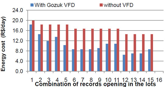 Notes that for the combinations where we had the same number of opened records, the power suffers no change, but when it is used ...
Notes that for the combinations where we had the same number of opened records, the power suffers no change, but when it is used ...Variable frequency drive on Cooling ...
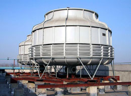 We are working on a study related to Cooling Towers. We want to decrease cooling water supply temperature going to steam ...
We are working on a study related to Cooling Towers. We want to decrease cooling water supply temperature going to steam ...VFD in China plantation irrigation ...
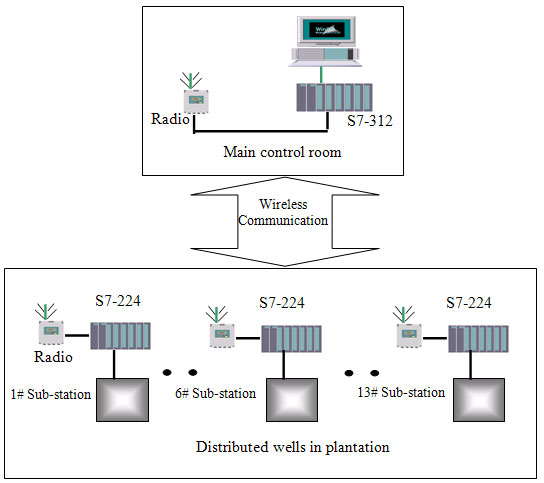 This article have a study of the wireless group control system with variable frequency drive (VFD) applied in a Chinese ...
This article have a study of the wireless group control system with variable frequency drive (VFD) applied in a Chinese ...VFD for pumps in variable flow water ...
Variable flow water system has played an important role in the field of energy saving with the VFD widely used in practical ...
Variable flow water system has played an important role in the field of energy saving with the VFD widely used in practical ...
VFD manufacturers