Home » Case study » Using variable frequency drive PID control for pump motor
Using variable frequency drive PID control for pump motor
Case: I want to control a motor (pump) speed via variable frequency drive in such a way that when temperature of the water increases the pump speed also increased and when temperature of the water decreases the speed of the motor (pump) also decreased. Can we used external PID control with a variable frequency drive OR use a variable frequency drive having a PID control option and then tune up that PID control?
The proportional gain or error amplification (P) is based on speed range to be employed, max temperature deviation accepted etc. like when you design a typical closed loop system. The integration time constant (I) is based on application response characteristics - you can say fairly trial and error input if one does not know the actual application response characteristics. - However the I time is not so difficult to tune - Apart from above you may as well ignore derivative constant (D) unless and until the application requires very fast response in case of large error which is not the case in this instance.
One option is to use a temperature sensor and a transmitter for temperature reading and use it directly for control in a variable frequency drive (VFD).
Another option is to hook it up to a control system like DCS. You can use PID controller in DCS for control. The output from DCS can be given to the VFD.
Advantages- Easy tuning, you can see and record trends. Better control. Also in case VFD fails you can simply replace the VFD. No need to enter the parameters and tune the loop again.
Disadvantages- Costly due to extra cables related cost and needs a control system to hook up to.
Using VFD for pumps are very common, you have to decide depending on the process criticality and resources available.
You should better go with external PID controller and control speed of VFD using PID controller output as it will give you better accuracy rather than using inbuilt PID control of VFD and in VFD you will have to use an transmitter to convert RTD signal to Voltage or current whereas you can easily use RTD in PID controller.
I like to make a small contribution, that you can add smart temperature transmitter which will convert RTD ohmic value to 4-20mA signal to your variable frequency drive as input signal. And VFD's PID will drive the operation.
Post a Comment:
You may also like:
Featured Articles
Variable frequency drive energy ...
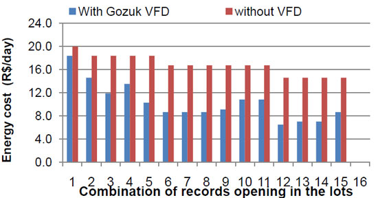 Notes that for the combinations where we had the same number of opened records, the power suffers no change, but when it is used ...
Notes that for the combinations where we had the same number of opened records, the power suffers no change, but when it is used ...Variable frequency drive on Cooling ...
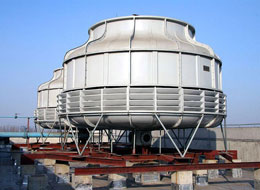 We are working on a study related to Cooling Towers. We want to decrease cooling water supply temperature going to steam ...
We are working on a study related to Cooling Towers. We want to decrease cooling water supply temperature going to steam ...VFD in China plantation irrigation ...
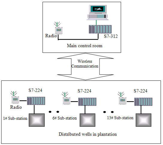 This article have a study of the wireless group control system with variable frequency drive (VFD) applied in a Chinese ...
This article have a study of the wireless group control system with variable frequency drive (VFD) applied in a Chinese ...VFD for pumps in variable flow water ...
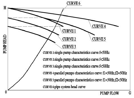 Variable flow water system has played an important role in the field of energy saving with the VFD widely used in practical ...
Variable flow water system has played an important role in the field of energy saving with the VFD widely used in practical ...
VFD manufacturers