Variable frequency drive Traverse function
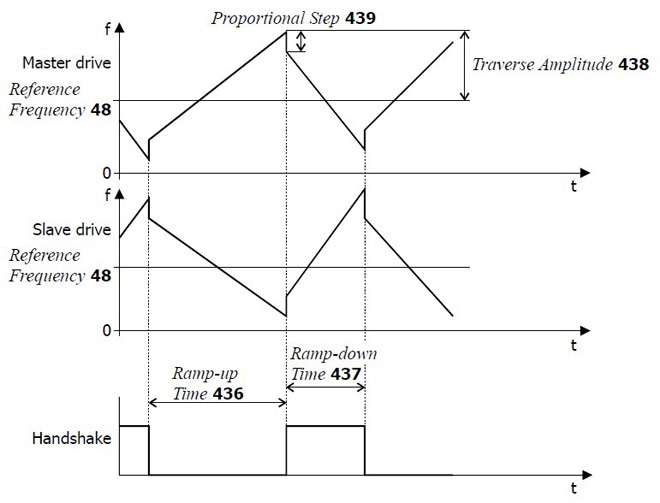
With the variable frequency drive traverse function, a triangle-shaped frequency signal with the start-up and shutdown times to be set is superimposed on the VFD output frequency. The resulting chronological order of the reference frequency of master VFD and slave VFD are shown in the following diagrams. The function can be used, for example, for VFDs which wind up thread on coils in textile machines. To avoid winding errors at the turning point of the thread guide, a proportional step is performed which causes a quick speed change.
In the case of the master variable frequency drive, the superimposed traverse frequency is linearly opposite to the limit Traverse Amplitude and then reverses the VFD direction. When the drives direction is reversed, a proportional step is effected. Via a handshake signal, the master VFD informs the slave VFD that the traverse output has changed its direction. The traverse function of the slave VFD has the same gradient as the traverse function of the master VFD, but an opposite sign. When the slave VFD reaches the limit Traverse Amplitude before switch-over of the handshake signal, the frequency is maintained until switch-over is effected. If the handshake signal is received before the frequency limit is reached, the variable frequency drive's direction is reversed immediately.
The Percentage values of Traverse Amplitude and Proportional Step refer to the current frequency value set up by Reference Frequency.

During the variable frequency drive traverse operation, the configured traverse parameter values cannot be changed. For traverse mode, the reference value source is selected via parameter Reference Frequency. Traverse mode becomes active when Operation Mode is switched on. In traverse mode, the values for Ramp-up Time and Ramp-down Time are active.
Attention:
The frequency range for traverse mode is added additional to the frequency reference. Therefore the added frequency can result in values smaller than the VFD Minimum Frequency or bigger than VFD Maximum Frequency.
In the case of the master variable frequency drive, the superimposed traverse frequency is linearly opposite to the limit Traverse Amplitude and then reverses the VFD direction. When the drives direction is reversed, a proportional step is effected. Via a handshake signal, the master VFD informs the slave VFD that the traverse output has changed its direction. The traverse function of the slave VFD has the same gradient as the traverse function of the master VFD, but an opposite sign. When the slave VFD reaches the limit Traverse Amplitude before switch-over of the handshake signal, the frequency is maintained until switch-over is effected. If the handshake signal is received before the frequency limit is reached, the variable frequency drive's direction is reversed immediately.
The Percentage values of Traverse Amplitude and Proportional Step refer to the current frequency value set up by Reference Frequency.

During the variable frequency drive traverse operation, the configured traverse parameter values cannot be changed. For traverse mode, the reference value source is selected via parameter Reference Frequency. Traverse mode becomes active when Operation Mode is switched on. In traverse mode, the values for Ramp-up Time and Ramp-down Time are active.
Attention:
The frequency range for traverse mode is added additional to the frequency reference. Therefore the added frequency can result in values smaller than the VFD Minimum Frequency or bigger than VFD Maximum Frequency.
Post a Comment:
You may also like:
Featured Articles
What is VFD, How it works? - VFD ...
 VFD is shorted for Variable Frequency Drive (also known as AC Drives and Inverters) -- that's used to make an AC motor working in ...
 VFD is shorted for Variable Frequency Drive (also known as AC Drives and Inverters) -- that's used to make an AC motor working in ...
VFD: Insulated Gate Bipolar Transistor ...
 IGBT (insulated gate bipolar transistor) provides a high switching speed necessary for PWM VFD operation. IGBTs are capable of ...
 IGBT (insulated gate bipolar transistor) provides a high switching speed necessary for PWM VFD operation. IGBTs are capable of ...
Three phase inverters
 In the variable frequency drive rectifier paper, it explains how to go from three phase alternating current voltage to a direct ...
 In the variable frequency drive rectifier paper, it explains how to go from three phase alternating current voltage to a direct ...
Variable Frequency Drive Harmonics and ...
A discussion of the benefits of variable frequency drives often leads to a question regarding electrical harmonic distortion ...
Variable frequency drive Energy saving
 Energy can be saved in a VFD by reducing the losses in the electric motor or by reducing the energy consumption of the variable ...
 Energy can be saved in a VFD by reducing the losses in the electric motor or by reducing the energy consumption of the variable ...
VFD manufacturers
