Home » Troubleshooting » Influence of VFD on motor shaft voltage and bearing currents
Influence of VFD on motor shaft voltage and bearing currents
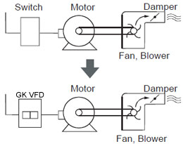
The advent of variable frequency drives (VFD) aggravated the phenomenon of induced shaft voltage/current, due to the unbalanced waveform and the high frequency components of the voltage supplied to the motor. The causes of shaft induced voltage owing to the PWM supply is thus added to those intrinsic to the motor (for instance, electromagnetic unbalance caused by asymmetries), which as well provoke current circulation through the bearings. The basic reason for bearing currents to occur within a variable frequency drive fed motor is the so called common mode voltage. The motor capacitive impedances become low in face of the high frequencies produced within the inverter stage of the variable frequency drive, causing current circulation through the path formed by rotor, shaft and bearings back to earth.
The three phase voltage supplied by the PWM variable frequency drive, differently from a purely sinusoidal voltage, is not balanced. That is, owing to the variable frequency drive stage topology, the vector sum of the instantaneous voltages of the three phases at the variable frequency drive output does not cancel out, but results in a high frequency electric potential relative to a common reference value (usually the earth or the negative bus of the DC link), hence the denomination "common mode".

The sum of the instantaneous voltage values at the (three phase) variable frequency drive output does not equal to zero.
This high frequency common mode voltage may result in undesirable common mode currents. Existing stray capacitances between motor and earth thus may allow current flowing to the earth, passing through rotor, shaft and bearings and reaching the end shield (earthed).
Practical experience shows that higher carrier frequencies tend to increase common mode voltages and currents.
Equivalent circuit of the motor for the high frequency capacitive currents
The high frequency model of the motor equivalent circuit, in which the bearings are represented by capacitances, shows the paths through which the common mode currents flow.
The rotor is supported by the bearings under a layer of non-conductive grease. At high speed operation there is no contact between the rotor and the (earthed) outer bearing raceway, due to the plain distribution of the grease. The electric potential of the rotor may then rise with respect to the earth until the dielectric strength of the grease film is disrupted, occurring voltage sparking and flow of discharge current through the bearings. This current that circulates whenever the grease film is momentarily broken down is often referred to as the capacitive discharge component. There is still another current component, which is induced by a ring flux in the stator yoke and circulates permanently through the characteristic conducting loop comprising the shaft, the end shields and the housing/frame, that is often called the conduction component.


Cer: Capacitor formed by the stator winding and the rotor lamination (Dielectric = air gap + slot insulation + wire insulation)
Crc : Capacitor formed by the rotor and the stator cores (Dielectric = air gap)
Cec: Capacitor formed by the stator winding and the frame (Dielectric = slot insulation + wire insulation)
Cmd e Cmt: Capacitances of the DE (drive end) and the NDE (non-drive end) bearings, formed by the inner and the outer bearing raceways, with the metallic rolling elements in the inside. (Dielectric = gaps between the raceways and the rolling elements + bearing grease)
ICM: Total common mode current
Ier: Capacitive discharge current flowing from the stator to the rotor
Ic: Capacitive discharge current flowing through the bearings
These discontinuous electric discharges wear the raceways and erode the rolling elements of the bearings, causing small superimposing punctures. Long term flowing discharge currents result in furrows (fluting), which reduce bearings life and may cause the machine to fail precociously.

Crater occasioned by electroerosion on the inner raceway of the bearing

Bearing raceway damaged by bearing currents flow

Fluting caused by electric discharges within the bearing
For the variable frequency drive fed motor bearing currents to be impeded to circulate, both the conduction (induced on the shaft) and the capacitive discharge (resultant from common mode voltage) components must be taken into account. In order to eliminate the current flowing through the characteristic conducting loop it is enough to isolate the motor bearings (only one of them, in the case of a single drive end, or the both of them, in the case of two drive ends). However, for the capacitive components to be withdrawn it would be also necessary to isolate the bearings of the driven machine, in order to avoid the migration of electric charges from the motor to the rotor of the driven machine through their shafts, which are electrically connected in the case of direct coupling. Another way of extinguishing the capacitive discharge current component consists of short circuiting the rotor and the motor frame by means of a sliding graphite brush. This way, the inductive current component flowing through the characteristic conducting loop can be eliminated by insulating just a single bearing of the motor, while the capacitive current component, as well as the transfer of capacitive charges to the driven machine, can be eliminated by use of a short circuiting brush.
Considerations about the current flowing through the bearings of variable frequency drive fed motors
Common mode voltage
The three phase voltage supplied by the PWM variable frequency drive, differently from a purely sinusoidal voltage, is not balanced. That is, owing to the variable frequency drive stage topology, the vector sum of the instantaneous voltages of the three phases at the variable frequency drive output does not cancel out, but results in a high frequency electric potential relative to a common reference value (usually the earth or the negative bus of the DC link), hence the denomination "common mode".
The sum of the instantaneous voltage values at the (three phase) variable frequency drive output does not equal to zero.
This high frequency common mode voltage may result in undesirable common mode currents. Existing stray capacitances between motor and earth thus may allow current flowing to the earth, passing through rotor, shaft and bearings and reaching the end shield (earthed).
Practical experience shows that higher carrier frequencies tend to increase common mode voltages and currents.
Equivalent circuit of the motor for the high frequency capacitive currents
The high frequency model of the motor equivalent circuit, in which the bearings are represented by capacitances, shows the paths through which the common mode currents flow.
The rotor is supported by the bearings under a layer of non-conductive grease. At high speed operation there is no contact between the rotor and the (earthed) outer bearing raceway, due to the plain distribution of the grease. The electric potential of the rotor may then rise with respect to the earth until the dielectric strength of the grease film is disrupted, occurring voltage sparking and flow of discharge current through the bearings. This current that circulates whenever the grease film is momentarily broken down is often referred to as the capacitive discharge component. There is still another current component, which is induced by a ring flux in the stator yoke and circulates permanently through the characteristic conducting loop comprising the shaft, the end shields and the housing/frame, that is often called the conduction component.
Cer: Capacitor formed by the stator winding and the rotor lamination (Dielectric = air gap + slot insulation + wire insulation)
Crc : Capacitor formed by the rotor and the stator cores (Dielectric = air gap)
Cec: Capacitor formed by the stator winding and the frame (Dielectric = slot insulation + wire insulation)
Cmd e Cmt: Capacitances of the DE (drive end) and the NDE (non-drive end) bearings, formed by the inner and the outer bearing raceways, with the metallic rolling elements in the inside. (Dielectric = gaps between the raceways and the rolling elements + bearing grease)
ICM: Total common mode current
Ier: Capacitive discharge current flowing from the stator to the rotor
Ic: Capacitive discharge current flowing through the bearings
These discontinuous electric discharges wear the raceways and erode the rolling elements of the bearings, causing small superimposing punctures. Long term flowing discharge currents result in furrows (fluting), which reduce bearings life and may cause the machine to fail precociously.
Crater occasioned by electroerosion on the inner raceway of the bearing
Bearing raceway damaged by bearing currents flow
Fluting caused by electric discharges within the bearing
Methods to reduce (or mitigate) the bearings currents in variable frequency drive fed motors
For the variable frequency drive fed motor bearing currents to be impeded to circulate, both the conduction (induced on the shaft) and the capacitive discharge (resultant from common mode voltage) components must be taken into account. In order to eliminate the current flowing through the characteristic conducting loop it is enough to isolate the motor bearings (only one of them, in the case of a single drive end, or the both of them, in the case of two drive ends). However, for the capacitive components to be withdrawn it would be also necessary to isolate the bearings of the driven machine, in order to avoid the migration of electric charges from the motor to the rotor of the driven machine through their shafts, which are electrically connected in the case of direct coupling. Another way of extinguishing the capacitive discharge current component consists of short circuiting the rotor and the motor frame by means of a sliding graphite brush. This way, the inductive current component flowing through the characteristic conducting loop can be eliminated by insulating just a single bearing of the motor, while the capacitive current component, as well as the transfer of capacitive charges to the driven machine, can be eliminated by use of a short circuiting brush.
Considerations about the current flowing through the bearings of variable frequency drive fed motors
- NEMA MG1 Part 31 – with sinusoidal supply shaft voltages may be present usually in motors of frame 500 and larger. (...) More recently, for some variable frequency drive types and application methods, potentially destructive bearing currents have occasionally occurred in much smaller motors. (...) The current path could be through either or both bearings to ground. Interruption of this current therefore requires insulating both bearings. Alternately, shaft grounding brushes may be used o divert the current around the bearing. It should be noted that insulating the motor bearings will not prevent the damage of other shaft connected equipment.
- NEMA Application Guide for AC variable frequency drive systems – the circulating currents caused by common mode voltage may cause bearing problems in frame sizes smaller than 500 (most likely in the 400 and larger frames).
- IEC 60034-17 – for machines with frame numbers above 315 it is recommended either to use an variable frequency drive with a filter designed to reduce the zero-sequence component of the phase voltages (so called common mode voltages) or to reduce the dV/dt of the voltage or to insulate the motor bearing(s). The need to insulate both motor bearings is seldom necessary. In such a case, the examination of the whole VFD system by an expert is highly recommended and should include the driven machine (insulation of the coupling) and the grounding system (possibly use of an earthing brush).
- IEC 60034-25 – do not specify a minimum frame size on which bearing protection must be applied. Within the clause broaching the effects of magnetic asymmetries as shaft voltages/bearing currents cause, it is mentioned that bearing currents commonly occur in motors above 440 kW. For other causes, no mention is made concerning frame sizes. According to the document, the solution adopted to avoid bearing currents depends on which current component is to be avoided. It may be made either by means of insulated bearings or shaft grounding system though.
- CSA 22.2 Nº100 Item 12 – shaft earthing brushes must be used in motors of frame above IEC 280 (NEMA 440).
- Gambica/REMA Technical Guide – for motors of frames below IEC 280 the effects of bearing currents are seldom appreciable and therefore no extra protection is needed. In such cases, adhering strictly to the motor and VFD manufacturers recommendations regarding the installation, cabling and grounding is enough. For frames above IEC 280, the effects of bearing currents may be significant and for security special protection is advisable. This may be obtained by means of insulated NDE bearing and shaft grounding system use. In such case, care must be taken not to bypass the bearing insulation.
Post a Comment:
You may also like:
Featured Articles
Non-Enclosure Variable Frequency Drive ...
 No enclosure (cover), reducing installation space and cost effective. Widely used in All-In-One control cabinet. Keep the same ...
No enclosure (cover), reducing installation space and cost effective. Widely used in All-In-One control cabinet. Keep the same ...Variable frequency drive application ...
 Variable Frequency Drive (VFD) can be used in lots of fields. Variable frequency drives are widely used to control the speed of ...
Variable Frequency Drive (VFD) can be used in lots of fields. Variable frequency drives are widely used to control the speed of ...Variable frequency drive in HVAC ...
 Variable frequency drives (VFD) have been used for HVAC systems in buildings for more than 40 years. But only in recent years, ...
Variable frequency drives (VFD) have been used for HVAC systems in buildings for more than 40 years. But only in recent years, ...Variable Frequency Drive Harmonics and ...
A discussion of the benefits of variable frequency drives often leads to a question regarding electrical harmonic distortion ...
Three phase inverters
 In the variable frequency drive rectifier paper, it explains how to go from three phase alternating current voltage to a direct ...
In the variable frequency drive rectifier paper, it explains how to go from three phase alternating current voltage to a direct ...
VFD manufacturers