Variable Frequency Drive Harmonics and Mitigation
A discussion of the benefits of variable frequency drives often leads to a question regarding electrical harmonic distortion problems. When evaluating variable frequency drives, it is important to understand how harmonics are provided and the circumstances under which harmonics are harmful.
In China, three-phase AC power typically operates at 50 hertz (50 cycles in one second). This is called the fundamental frequency.
A harmonic is any current form at an integral multiple of the fundamental frequency. For example, for 50-hertz power supplies, harmonics would be at 100 hertz (2 x fundamental), 150 hertz, 200 hertz, 250 hertz, etc.
What Causes Harmonics?
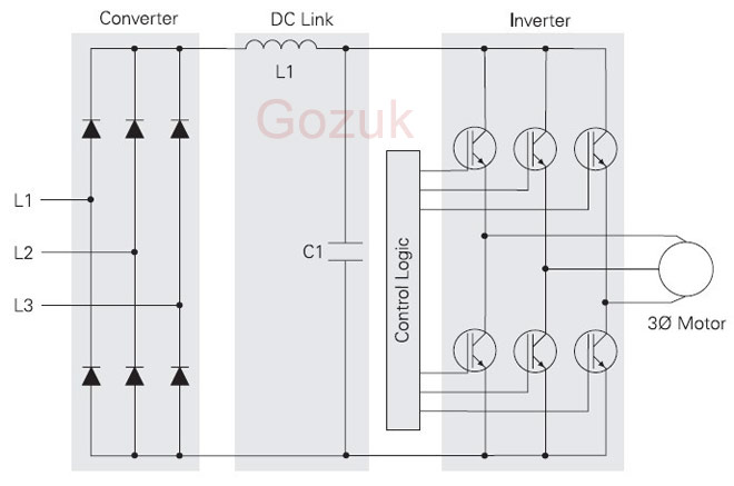
Variable frequency drives draw current from the line only when the line voltage is greater than the DC Bus voltage inside the VFD. This occurs only near the peaks of the sine wave. As a result, all of the current is drawn in short intervals (i.e., at higher frequencies). Variation in variable frequency drive design affects the harmonics produced. For example, variable frequency drives equipped with DC link inductors produce different levels of harmonics than similar variable frequency drives without DC link inductors. The variable frequency drive with active front end utilizing transistors in the rectifier section have much lower harmonic levels than variable frequency drives using diodes or silicon controlled rectifiers (SCRs).
Electronic lighting ballasts, uninterruptible power supplies, computers, office equipment, ozone generators, and other high intensity lighting are also sources of harmonic problems.
Rocks and Ponds
Obviously, the magnitude of the contributing wave forms has an effect on the shape of the resultant wave form. If the fundamental wave form (50 Hz) has a very large magnitude (5,000 amps) and the harmonic wave forms are very low (10 amps), then the resultant wave form will not be very distorted and total harmonic distortion will be low. If the harmonic wave form current value is high relative to the fundamental, the effect will be more dramatic.
In nature, we see this effect with waves in water. If you continually throw baseball size rocks into the ocean, you would not expect to change the shape of the waves crashing onto the beach. However, if you threw those same size rocks into a bathtub, you would definitely observe the effects. It is similar with electrical waves and harmonic distortion.
When you calculate harmonics you are calculating the effect of the harmonics on the fundamental current wave form in a particular distribution system. There are several programs that can perform estimated calculations. All of them take into account the amount of linear loads (loads drawing power through out the entire sine wave) relative to non-linear loads (loads drawing power during only a fraction of the sine wave). The higher the ratio of linear loads to non-linear loads, the less effect the non-linear loads will have on the current wave form.
Harmonics that are multiples of 2 are not harmful because they cancel out. The same is true for 3rd order harmonics (3rd, 6th, 9th etc.). Because the power supply is 3 phase, the third order harmonics cancel each other out in each phase. This leaves only the 5th, 7th, 11th, 13th etc. to discuss. The magnitude of the harmonics produced by a variable frequency drive is greatest for the lower order harmonics (5th, 7th and 11th) and drops quickly as you move into the higher order harmonics (13th and greater).
Harmonics can cause some problems in electrical systems. Higher order harmonics can interfere with sensitive electronics and communications systems, while lower order harmonics can cause overheating of motors, transformers, and conductors. The opportunity for harmonics to be harmful, however, is dependent upon the electrical system in which they are present and whether or not any harmonic sensitive equipment is located on that same electrical system.
Understanding IEEE 519
IEEE (Institute of Electrical and Electronics Engineers) created a recommendation for calculating harmonics. The IEEE-519 standard provides recommended limits for harmonic distortion measured at the point of common coupling. The point of common coupling is the point at which the customer's electrical system is connected to the utility.
Although the IEEE standard recommends limits for both voltage distortion and current distortion, specifications that reference a 5% harmonic limitation are generally referring to current distortion. In most cases, if the current distortion falls within IEEE-519 requirements, the voltage distortion will also be acceptable.
Determining compliance with IEEE-519 requires an actual measurement of the system during operation. Predicting compliance in advance often requires a system study that accounts for all electrical equipment (transformers, wires, motors, variable frequency drives, etc.) in the system.
Harmonic Terms
Total Harmonic Voltage Distortion - THD (V)
As harmonic currents flow through devices with reactance or resistance, a voltage drop is developed. These harmonic voltages cause voltage distortion of the fundamental voltage wave form. The total magnitude of the voltage distortion is the THD (V). The IEEE-519 standard recommends less than 5% THD (V) at the point of common coupling for general systems 69 kV and under.
Total Harmonic Current Distortion - THD (I)
This value (sometimes written as THID) represents the total harmonic current distortion of the wave form at the particular moment when the measurement is taken. It is the ratio of the harmonic current to the fundamental (non-harmonic) current measured for that load point. Note that the denominator used in this ratio changes with load.
Total Demand Distortion - TDD
Total Demand Distortion (TDD) is the ratio of the measured harmonic current to the full load fundamental current. The full load fundamental current is the total amount of non-harmonic current consumed by all of the loads on the system when the system is at peak demand. The denominator used in this ratio does not change with load. Although TDD can be measured at any operating point (full or part load), the worst case TDD will occur at full load. If the full load TDD is acceptable, then the TDD measured at part load values will also be acceptable. To use our rock analogy, the full load fundamental current is the size of our pond and the harmonic current is the size of our rock. (See Table 1.)
Table 1. Comparison of TDD and THD(I)
TDD - Total Demand Distortion
THD(I) - Total Harmonic Current Distortion
Short Circuit Ratio
Short circuit ratio is the short circuit current value of the electrical system divided by its maximum load current. Standard IEEE-519 Table 10.3 defines different acceptance levels of TDD depending on the short circuit ratio in the system. Systems with small short circuit ratios have lower TDD requirements than systems with larger short circuit ratios. This difference accounts for the fact that electrical systems with low short circuit ratios tend to have high impedances, creating larger voltage distortion for equivalent harmonic current levels. (See Table 2.)
Table 2. Representation of IEEE Table 10.3
LEGEND: h = harmonic number
ISC = maximum short-circuit current at PCC
IL = maximum demand load current (fundamental) at PCC
Some utilities now impose penalties for introducing harmonics onto their grid, providing incentives for owners to reduce harmonics. In addition, reducing harmonic levels can prevent potential problems to sensitive equipment residing on the same system. There are many approaches to mitigating harmonics. Several commonly used methods are discussed here.
Line Reactors
Line reactor adds reactance and impedance to the circuit. Reactance and impedance act to lower the current magnitude of harmonics in the system and thereby lower the TDD. Line reactors also protect devices from large current spikes with short rise times. A line reactor placed between the variable frequency drive and the motor would help protect the motor from current spikes. A line reactor placed between the supply and variable frequency drive would help protect the supply from current spikes. Line reactors are typically only used between the variable frequency drive and the motor when a freestanding variable frequency drive is mounted more than fifty feet from the motor. This is done to protect the motor windings from voltage peaks with extremely quick rise times.
Passive Filters
Trap Filters are devices that include an electrical circuit consisting of inductors, reactors, and capacitors designed to provide a low impedance path to ground at the targeted frequency. Since current will travel through the lowest impedance path, this prevents the harmonic current at the targeted frequency from propagating through the system. Filters can be mounted inside the VFD panel or as free standing devices. Trap filters are typically quoted to meet a THD(I) value that would result in compliance with IEEE-519 requirements if the system were otherwise already in compliance.
Active Filters
Some devices measure harmonic currents and quickly create opposite current harmonic wave forms. The two wave forms then cancel out, preventing harmonic currents from being observed upstream of the filter. These types of filters generally have excellent harmonic mitigation characteristics. Active filters may reduce generator size requirements.
Variable frequency drives using Active Front End Technology (AFE)
Some variable frequency drives are manufactured with IGBT rectifiers. The unique attributes of IGBTs allow the variable frequency drive to actively control the power input, thereby lowering harmonics, increasing power factor and making the variable frequency drive far more tolerant of supply side disturbances. The AFE variable frequency drives have ultra low harmonics capable of meeting IEEE-519 standards without any external filters or line reactors. This significantly reduces installation cost and generator size requirements. An AFE VFD provides the best way to take advantages of variable frequency drive and minimize harmonics.
Multi-Pulse Variable frequency drives (Cancellation)
There are a minimum of six rectifiers for a three phase variable frequency drive. There can be more, however. Basically manufacturers offer 12, 18, 24, and 30 pulse VFDs. A standard six-pulse VFD has six rectifiers, a 12-pulse VFD has two sets of six rectifiers, an 18-pulse VFD has three sets of six rectifiers and so on. If the power connected to each set of rectifiers is phase shifted, then some of the harmonics produced by one set of rectifiers will be opposite in polarity from the harmonics produced by the other set of rectifiers. The two wave forms effectively cancel each other out. In order to use phase shifting, a special transformer with multiple secondary windings must be used. For example, with a 12-pulse variable frequency drive, a Delta/Delta-Wye transformer with each of the secondary phases shifted by 30 degrees would be used.
Harmonic Definition
In China, three-phase AC power typically operates at 50 hertz (50 cycles in one second). This is called the fundamental frequency.
A harmonic is any current form at an integral multiple of the fundamental frequency. For example, for 50-hertz power supplies, harmonics would be at 100 hertz (2 x fundamental), 150 hertz, 200 hertz, 250 hertz, etc.
What Causes Harmonics?
Variable frequency drives draw current from the line only when the line voltage is greater than the DC Bus voltage inside the VFD. This occurs only near the peaks of the sine wave. As a result, all of the current is drawn in short intervals (i.e., at higher frequencies). Variation in variable frequency drive design affects the harmonics produced. For example, variable frequency drives equipped with DC link inductors produce different levels of harmonics than similar variable frequency drives without DC link inductors. The variable frequency drive with active front end utilizing transistors in the rectifier section have much lower harmonic levels than variable frequency drives using diodes or silicon controlled rectifiers (SCRs).
Electronic lighting ballasts, uninterruptible power supplies, computers, office equipment, ozone generators, and other high intensity lighting are also sources of harmonic problems.
Rocks and Ponds
Obviously, the magnitude of the contributing wave forms has an effect on the shape of the resultant wave form. If the fundamental wave form (50 Hz) has a very large magnitude (5,000 amps) and the harmonic wave forms are very low (10 amps), then the resultant wave form will not be very distorted and total harmonic distortion will be low. If the harmonic wave form current value is high relative to the fundamental, the effect will be more dramatic.
In nature, we see this effect with waves in water. If you continually throw baseball size rocks into the ocean, you would not expect to change the shape of the waves crashing onto the beach. However, if you threw those same size rocks into a bathtub, you would definitely observe the effects. It is similar with electrical waves and harmonic distortion.
When you calculate harmonics you are calculating the effect of the harmonics on the fundamental current wave form in a particular distribution system. There are several programs that can perform estimated calculations. All of them take into account the amount of linear loads (loads drawing power through out the entire sine wave) relative to non-linear loads (loads drawing power during only a fraction of the sine wave). The higher the ratio of linear loads to non-linear loads, the less effect the non-linear loads will have on the current wave form.
Are Harmonics Cause Problems?
Harmonics that are multiples of 2 are not harmful because they cancel out. The same is true for 3rd order harmonics (3rd, 6th, 9th etc.). Because the power supply is 3 phase, the third order harmonics cancel each other out in each phase. This leaves only the 5th, 7th, 11th, 13th etc. to discuss. The magnitude of the harmonics produced by a variable frequency drive is greatest for the lower order harmonics (5th, 7th and 11th) and drops quickly as you move into the higher order harmonics (13th and greater).
Harmonics can cause some problems in electrical systems. Higher order harmonics can interfere with sensitive electronics and communications systems, while lower order harmonics can cause overheating of motors, transformers, and conductors. The opportunity for harmonics to be harmful, however, is dependent upon the electrical system in which they are present and whether or not any harmonic sensitive equipment is located on that same electrical system.
Understanding IEEE 519
IEEE (Institute of Electrical and Electronics Engineers) created a recommendation for calculating harmonics. The IEEE-519 standard provides recommended limits for harmonic distortion measured at the point of common coupling. The point of common coupling is the point at which the customer's electrical system is connected to the utility.
Although the IEEE standard recommends limits for both voltage distortion and current distortion, specifications that reference a 5% harmonic limitation are generally referring to current distortion. In most cases, if the current distortion falls within IEEE-519 requirements, the voltage distortion will also be acceptable.
Determining compliance with IEEE-519 requires an actual measurement of the system during operation. Predicting compliance in advance often requires a system study that accounts for all electrical equipment (transformers, wires, motors, variable frequency drives, etc.) in the system.
Harmonic Terms
Total Harmonic Voltage Distortion - THD (V)
As harmonic currents flow through devices with reactance or resistance, a voltage drop is developed. These harmonic voltages cause voltage distortion of the fundamental voltage wave form. The total magnitude of the voltage distortion is the THD (V). The IEEE-519 standard recommends less than 5% THD (V) at the point of common coupling for general systems 69 kV and under.
Total Harmonic Current Distortion - THD (I)
This value (sometimes written as THID) represents the total harmonic current distortion of the wave form at the particular moment when the measurement is taken. It is the ratio of the harmonic current to the fundamental (non-harmonic) current measured for that load point. Note that the denominator used in this ratio changes with load.
Total Demand Distortion - TDD
Total Demand Distortion (TDD) is the ratio of the measured harmonic current to the full load fundamental current. The full load fundamental current is the total amount of non-harmonic current consumed by all of the loads on the system when the system is at peak demand. The denominator used in this ratio does not change with load. Although TDD can be measured at any operating point (full or part load), the worst case TDD will occur at full load. If the full load TDD is acceptable, then the TDD measured at part load values will also be acceptable. To use our rock analogy, the full load fundamental current is the size of our pond and the harmonic current is the size of our rock. (See Table 1.)
Table 1. Comparison of TDD and THD(I)
|
Fundamental Current (rms) |
Harmonic Current (rms) |
THD(I) |
THD |
|
1000 |
50 |
5% |
5% |
|
800 |
43.8 |
5.4% |
4.4% |
|
600 |
36.3 |
6.1% |
3.6% |
|
400 |
29.7 |
7.4% |
3.0% |
|
200 |
20.0 |
10% |
2% |
|
100 |
13.4 |
13.4% |
1.3% |
THD(I) - Total Harmonic Current Distortion
Short Circuit Ratio
Short circuit ratio is the short circuit current value of the electrical system divided by its maximum load current. Standard IEEE-519 Table 10.3 defines different acceptance levels of TDD depending on the short circuit ratio in the system. Systems with small short circuit ratios have lower TDD requirements than systems with larger short circuit ratios. This difference accounts for the fact that electrical systems with low short circuit ratios tend to have high impedances, creating larger voltage distortion for equivalent harmonic current levels. (See Table 2.)
Table 2. Representation of IEEE Table 10.3
|
ISC/IL |
<11 |
11<h<17 |
17<h<23 |
23<h<35 |
35<h |
TDD |
|
<20 |
4 |
2 |
1.5 |
0.6 |
0.3 |
5 |
|
20<50 |
7 |
3.5 |
2.5 |
1 |
0.5 |
8 |
|
50<100 |
10 |
4.5 |
4 |
1.5 |
0.7 |
12 |
|
100<1000 |
12 |
5.5 |
5 |
2 |
1 |
15 |
|
>1000 |
15 |
7 |
6 |
2.5 |
1.4 |
20 |
ISC = maximum short-circuit current at PCC
IL = maximum demand load current (fundamental) at PCC
Harmonics Mitigation
Some utilities now impose penalties for introducing harmonics onto their grid, providing incentives for owners to reduce harmonics. In addition, reducing harmonic levels can prevent potential problems to sensitive equipment residing on the same system. There are many approaches to mitigating harmonics. Several commonly used methods are discussed here.
Line Reactors
Line reactor adds reactance and impedance to the circuit. Reactance and impedance act to lower the current magnitude of harmonics in the system and thereby lower the TDD. Line reactors also protect devices from large current spikes with short rise times. A line reactor placed between the variable frequency drive and the motor would help protect the motor from current spikes. A line reactor placed between the supply and variable frequency drive would help protect the supply from current spikes. Line reactors are typically only used between the variable frequency drive and the motor when a freestanding variable frequency drive is mounted more than fifty feet from the motor. This is done to protect the motor windings from voltage peaks with extremely quick rise times.
Passive Filters
Trap Filters are devices that include an electrical circuit consisting of inductors, reactors, and capacitors designed to provide a low impedance path to ground at the targeted frequency. Since current will travel through the lowest impedance path, this prevents the harmonic current at the targeted frequency from propagating through the system. Filters can be mounted inside the VFD panel or as free standing devices. Trap filters are typically quoted to meet a THD(I) value that would result in compliance with IEEE-519 requirements if the system were otherwise already in compliance.
Active Filters
Some devices measure harmonic currents and quickly create opposite current harmonic wave forms. The two wave forms then cancel out, preventing harmonic currents from being observed upstream of the filter. These types of filters generally have excellent harmonic mitigation characteristics. Active filters may reduce generator size requirements.
Variable frequency drives using Active Front End Technology (AFE)
Some variable frequency drives are manufactured with IGBT rectifiers. The unique attributes of IGBTs allow the variable frequency drive to actively control the power input, thereby lowering harmonics, increasing power factor and making the variable frequency drive far more tolerant of supply side disturbances. The AFE variable frequency drives have ultra low harmonics capable of meeting IEEE-519 standards without any external filters or line reactors. This significantly reduces installation cost and generator size requirements. An AFE VFD provides the best way to take advantages of variable frequency drive and minimize harmonics.
Multi-Pulse Variable frequency drives (Cancellation)
There are a minimum of six rectifiers for a three phase variable frequency drive. There can be more, however. Basically manufacturers offer 12, 18, 24, and 30 pulse VFDs. A standard six-pulse VFD has six rectifiers, a 12-pulse VFD has two sets of six rectifiers, an 18-pulse VFD has three sets of six rectifiers and so on. If the power connected to each set of rectifiers is phase shifted, then some of the harmonics produced by one set of rectifiers will be opposite in polarity from the harmonics produced by the other set of rectifiers. The two wave forms effectively cancel each other out. In order to use phase shifting, a special transformer with multiple secondary windings must be used. For example, with a 12-pulse variable frequency drive, a Delta/Delta-Wye transformer with each of the secondary phases shifted by 30 degrees would be used.
Variable frequency drives using Active Front End Technology (AFE)- If a VFD uses IGBT with a system voltage of 6.6KV and Motor HP at 6000HP, are filter required to meet IEEE-519
Post a Comment:
You may also like:
Featured Articles
Variable frequency drive Rectifier
 To understand variable frequency drive (VFD) better, it's necessary to explain some of the main parts of the variable frequency ...
To understand variable frequency drive (VFD) better, it's necessary to explain some of the main parts of the variable frequency ...VFD controlled Induction motor ...
 This paper presents a procedure to measure the efficiency on an induction motor fed by a VFD by the all operation range to speed ...
This paper presents a procedure to measure the efficiency on an induction motor fed by a VFD by the all operation range to speed ...What is VFD, How it works? - VFD ...
 VFD is shorted for Variable Frequency Drive (also known as AC Drives and Inverters) -- that's used to make an AC motor working in ...
VFD is shorted for Variable Frequency Drive (also known as AC Drives and Inverters) -- that's used to make an AC motor working in ...VFD: Insulated Gate Bipolar Transistor ...
 IGBT (insulated gate bipolar transistor) provides a high switching speed necessary for PWM VFD operation. IGBTs are capable of ...
IGBT (insulated gate bipolar transistor) provides a high switching speed necessary for PWM VFD operation. IGBTs are capable of ...VFD: Pulse Width Modulation (PWM)
 Pulse Width Modulation (PWM) VFDs provide a more sinusoidal current output to control frequency and voltage supplied to an AC ...
Pulse Width Modulation (PWM) VFDs provide a more sinusoidal current output to control frequency and voltage supplied to an AC ...
VFD manufacturers