Three phase inverters
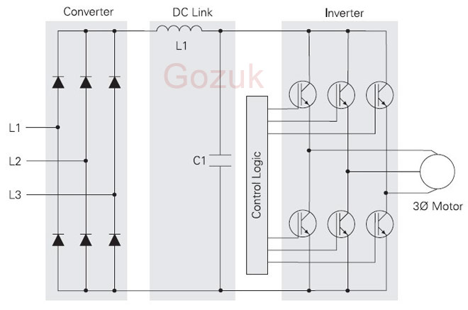
In the variable frequency drive rectifier paper, it explains how to go from three phase alternating current voltage to a direct current voltage by means of a rectifying circuit. The three phase bridge inverter with six diodes seemed a good starting point to convert AC to DC. In this paper the opposite process is described. When a DC source (voltage or current) is available an inverter can be used to convert the energy to an AC source. When the source is a direct current source a current source inverter is needed, when it is a DC voltage source a constant or variable voltage source inverter can be used. The direct current source has not so many applications so it will not be described.
Principle
To invert the direct current voltage to alternating current voltage the opposite process of the rectifying process should be done. The problem is here that the natural commutations processes are not available and by that the use of passive semiconductors like diodes can not be used. To explain the process idealized switches are used. That means no switching losses, unlimited switching frequency, no switching delay and so on. In a real circuit several options are available, dependent on the needed frequency, power or other important characteristics of the load. There are several methods to steer the inverter bridge but here the description is narrowed to the 180°-inverter principle. In the 180°-inverter there are at every moment three switches closed and three open. The principle is showed in following Figure.

Of course the three closed switches are never in the same bridge half. The following graphs, formulas and comments are in the assumption of a symmetric three phase load like an induction motor. To come to the graphs of following Figure several steps are made.

Line wire one, indicated by L1 may never be connected with both positive and negative potential at once because this gives obviously a short circuit. The name 180°-inverter indicates that the switches are in one period closed for 180° and logically open for the remaining 180°. With t his in mind the graph of uL1 can be found. It gives t he potential from line L1 in reference to the negative pole of the direct current voltage source. The principle is to get a symmetric process with no short circuits or points where the three switches of the same bridge half are together closed. Here for the switching process of the other lines is similar but the course of voltage uL2 is 120° shifted and the course of voltage uL3 is shifted 240° according to uL1 With this in mind three line voltages can be defined. Line voltage uL1 L2 is the potential between line wire L1 and line wire L2 or maybe more easy to see the difference between uL1 and uL2 Line voltages uL2 L3 and uL3 L1 are defined analogue as the difference between u 1,2 and u1,3 respectively the difference between uL3 and uL1 Like showed in the lowest graphs of Figure klklk the line voltages are block shaped. The numbering of the switches is standard and analogue as the numbering of the diodes in a rectifier. By this at every moment three consecutive switches are in conducting state.
Voltage wave shape
A symmetric load on the three phase output of the inverter can be a star load or a delta load. For the delta load the phase voltages of load are identical to the line voltages of the inverter. But when the load is a star load the shape of the line voltages are no longer block shaped. It is easily to see that the line voltages than get a stepped course. This voltage is a better approach of an actual sinus. Further based on the Figure can be made to determine the phase voltages graphically. When for instance situation 0 < t < T /6 is simplified like showed in Figure. The different potentials in this situation are easy to find with the Kirchhoff's law. The load, here an induction motor is taken, is symmetric so that

There the motor coils are inductive loads, the form of the current will be exponential when the voltage has a stepped shape. Because the connection of the two switches in the same phase would give a short circuit and the switches (even when they are electronic) are not ideal, a dead time td between the opening of the one and the closing of the other is needed.
Harmonics
Because the voltage has a blocked or stepped course, the harmonic content of the signals is high. Based on the theorem of Fourier these signals can be found . The blocked course is symmetric in time (symmetry according to ordinate) and symmetric per half period. By that the Fourier analysis includes only cosine, odd terms. The further deduct the formula next steps are taken:

The part between parentheses becomes zero for terms that are a multiple of two or three so that only terms with n = 6k ± 1 and the ground harmonic remains. For these terms the part between parentheses becomes ±√3. This gives the end formula:

The part between parentheses becomes zero for terms that are a multiple of two or three so that only terms with n = 6k ± 1 and the ground harmonic remains. For these terms the part between parentheses becomes ±3. This gives the end formula:
Pulse width modulation
From previous chapter is cl ear that the 180° steering of the inverter bridge causes too many harmonics. The control of the speed of an induction motor by varying the frequency of a 180° steering is thus not the ideal solution. Another possibility is the variation of the pulse width to get a better approach of the sine wave. This technique is called pulse width modulation. The operation of the pulse width modulation inverter, often shortened to PWM, can be explained with use of following Figure.

In this example a triangle wave with frequency fd is compared with a symmetric three phase sine wave system. The intersections of the triangular wave, also called carrier, with the sine waves determines the steering of the three phase inverter bridge. In the figure the intersections A, C, E, G and I indicate when switch 1 has to close while switch 4 is open. The intersections B, D, F and H indicate when switch 1 has to open while switch 4 has to close after a dead time td . The same procedure is applied to the other sine waves and switches. The voltages ux and uy give the line voltages at L1 and L2. The width of the pulses in these voltage signals follows a sine course. This is sinusoidal PWM. The signals x and Y are called the modulators because their frequency f1 modulates the frequency of the phase voltages. The ratio between the frequency of the triangular wave and the modulator sine is called the pulse number:
From the Figure (d), which gives the line voltage uL1 L2, it is clear that the output signal isn't a smooth sine wave and it will thus contain also harmonics. The maximum of the triangular wave is synchronized with the maximum from the three sine modulators. This is called synchronous modulation. Because of this the intersections of modulator and carrier are more easily found.
Principle
To invert the direct current voltage to alternating current voltage the opposite process of the rectifying process should be done. The problem is here that the natural commutations processes are not available and by that the use of passive semiconductors like diodes can not be used. To explain the process idealized switches are used. That means no switching losses, unlimited switching frequency, no switching delay and so on. In a real circuit several options are available, dependent on the needed frequency, power or other important characteristics of the load. There are several methods to steer the inverter bridge but here the description is narrowed to the 180°-inverter principle. In the 180°-inverter there are at every moment three switches closed and three open. The principle is showed in following Figure.
Of course the three closed switches are never in the same bridge half. The following graphs, formulas and comments are in the assumption of a symmetric three phase load like an induction motor. To come to the graphs of following Figure several steps are made.
Line wire one, indicated by L1 may never be connected with both positive and negative potential at once because this gives obviously a short circuit. The name 180°-inverter indicates that the switches are in one period closed for 180° and logically open for the remaining 180°. With t his in mind the graph of uL1 can be found. It gives t he potential from line L1 in reference to the negative pole of the direct current voltage source. The principle is to get a symmetric process with no short circuits or points where the three switches of the same bridge half are together closed. Here for the switching process of the other lines is similar but the course of voltage uL2 is 120° shifted and the course of voltage uL3 is shifted 240° according to uL1 With this in mind three line voltages can be defined. Line voltage uL1 L2 is the potential between line wire L1 and line wire L2 or maybe more easy to see the difference between uL1 and uL2 Line voltages uL2 L3 and uL3 L1 are defined analogue as the difference between u 1,2 and u1,3 respectively the difference between uL3 and uL1 Like showed in the lowest graphs of Figure klklk the line voltages are block shaped. The numbering of the switches is standard and analogue as the numbering of the diodes in a rectifier. By this at every moment three consecutive switches are in conducting state.
Voltage wave shape
A symmetric load on the three phase output of the inverter can be a star load or a delta load. For the delta load the phase voltages of load are identical to the line voltages of the inverter. But when the load is a star load the shape of the line voltages are no longer block shaped. It is easily to see that the line voltages than get a stepped course. This voltage is a better approach of an actual sinus. Further based on the Figure can be made to determine the phase voltages graphically. When for instance situation 0 < t < T /6 is simplified like showed in Figure. The different potentials in this situation are easy to find with the Kirchhoff's law. The load, here an induction motor is taken, is symmetric so that
uc1 = 1/3 Ut, uc2 = 2/3 Ut, uc3 = 1/3 Ut,The different voltage levels that are possible in the coils are
±(Ut / 3) or ±(2Ut / 3)
There the motor coils are inductive loads, the form of the current will be exponential when the voltage has a stepped shape. Because the connection of the two switches in the same phase would give a short circuit and the switches (even when they are electronic) are not ideal, a dead time td between the opening of the one and the closing of the other is needed.
Harmonics
Because the voltage has a blocked or stepped course, the harmonic content of the signals is high. Based on the theorem of Fourier these signals can be found . The blocked course is symmetric in time (symmetry according to ordinate) and symmetric per half period. By that the Fourier analysis includes only cosine, odd terms. The further deduct the formula next steps are taken:
The part between parentheses becomes zero for terms that are a multiple of two or three so that only terms with n = 6k ± 1 and the ground harmonic remains. For these terms the part between parentheses becomes ±√3. This gives the end formula:
For the stepped course an analogue app1roach can be made. There are also only odd cosine terms for the same reason. The amplitude of the different terms is as follows:
The part between parentheses becomes zero for terms that are a multiple of two or three so that only terms with n = 6k ± 1 and the ground harmonic remains. For these terms the part between parentheses becomes ±3. This gives the end formula:
Pulse width modulation
From previous chapter is cl ear that the 180° steering of the inverter bridge causes too many harmonics. The control of the speed of an induction motor by varying the frequency of a 180° steering is thus not the ideal solution. Another possibility is the variation of the pulse width to get a better approach of the sine wave. This technique is called pulse width modulation. The operation of the pulse width modulation inverter, often shortened to PWM, can be explained with use of following Figure.
In this example a triangle wave with frequency fd is compared with a symmetric three phase sine wave system. The intersections of the triangular wave, also called carrier, with the sine waves determines the steering of the three phase inverter bridge. In the figure the intersections A, C, E, G and I indicate when switch 1 has to close while switch 4 is open. The intersections B, D, F and H indicate when switch 1 has to open while switch 4 has to close after a dead time td . The same procedure is applied to the other sine waves and switches. The voltages ux and uy give the line voltages at L1 and L2. The width of the pulses in these voltage signals follows a sine course. This is sinusoidal PWM. The signals x and Y are called the modulators because their frequency f1 modulates the frequency of the phase voltages. The ratio between the frequency of the triangular wave and the modulator sine is called the pulse number:
N = fd / f1The ratio between the amplitude of the sine modulator uM and the amplitude of the triangular wave Ud is the modulation depth:
m = uM / UdThe output line voltage UL1 L2 can be formulated in relation to the modulation depth as follows:
UL1 L2 = m (√3Ut / 2√2)As long as 0 < m ≤ 1 the effective value of the output voltage increases linear with the modulation depth with a maximum of
(√3 / 2√2)Ut ≈ 0.612 UtWhen the modulation depth exceeds 1 the signal is over modulated and will converge to a block wave with effective value
(√6 / π)Ut ≈ 0.78 UtHarmonics in PWM-wave
From the Figure (d), which gives the line voltage uL1 L2, it is clear that the output signal isn't a smooth sine wave and it will thus contain also harmonics. The maximum of the triangular wave is synchronized with the maximum from the three sine modulators. This is called synchronous modulation. Because of this the intersections of modulator and carrier are more easily found.
Post a Comment:
You may also like:
Featured Articles
Variable frequency drive Rectifier
 To understand variable frequency drive (VFD) better, it's necessary to explain some of the main parts of the variable frequency ...
To understand variable frequency drive (VFD) better, it's necessary to explain some of the main parts of the variable frequency ...VFD controlled Induction motor ...
 This paper presents a procedure to measure the efficiency on an induction motor fed by a VFD by the all operation range to speed ...
This paper presents a procedure to measure the efficiency on an induction motor fed by a VFD by the all operation range to speed ...VFD: Pulse Width Modulation (PWM)
 Pulse Width Modulation (PWM) VFDs provide a more sinusoidal current output to control frequency and voltage supplied to an AC ...
Pulse Width Modulation (PWM) VFDs provide a more sinusoidal current output to control frequency and voltage supplied to an AC ...Variable frequency drive Advantages & ...
VFDs are good for variable speed, in a water pump this is used to maintain a steady pressure, they will smooth out variances in ...
Variable frequency drive Energy saving
 Energy can be saved in a VFD by reducing the losses in the electric motor or by reducing the energy consumption of the variable ...
Energy can be saved in a VFD by reducing the losses in the electric motor or by reducing the energy consumption of the variable ...
VFD manufacturers