VFD Control Strategies
A computer program connected to the VFD or a human machine interface (HMI) front panel enables inputting data about the load and the motor as well as setting the VFD control strategy, which usually takes advantage of proprietary functionality. This variable frequency drives strategy together with the load dynamic behavior determines performance. Loops within the VFD electronics can be configured to control speed (through an external encoder), voltage, current and, in some cases, motor flux. These are the inner loops of the process control cascade. When tuning, remember that the inner loops must be at least five times more responsive than the outer loop. Another term to describe performance is bandwidth; it's inversely proportional to the time constant of the controller/motor with no load.
Variable frequency drive manufacturers offer models with varying performance and cost. So, assess which is the best VFD for the particular application.
Most VFDs have a defined, configured startup sequence that is to be run with the load disconnected. During this sequence the VFD powers the stator and makes measurements that determine the characteristics of the motor. These motor constants then are used to tune the internal electronic program.
VFD control strategies generally fall into three categories:
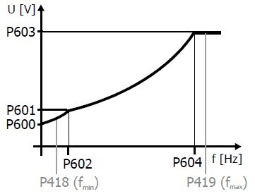
Volts per Hertz control. This is the simplest method. As seen in the torque speed curve, the region to the right of the peak can be considered linear — therefore controlling the frequency will regulate the shaft speed. The VFD supplied voltage is v = ir + dλ/dt, where λ is the flux linkage. The derivative term is directly related to the rotation; so the rotational speed is proportional to voltage, thereby volts per hertz. At high speeds the ir term is negligible. The speed error is large at less than 10% of the rated rpm. Some configurations can compensate for this. This VFD strategy is recommended for fan and pump applications, in a variable frequency drive controlled pump, energy saving is significant. The resolution is about 0.5% base speed over a 40:1 range.
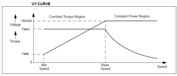
Another problem with this VFD strategy is the reduced motor torque at low speeds. This can be a serious problem conveying sticky solids or slurries. The torque decreases because the motor and wire ir drop is a larger percentage of the supplied power. Using a larger wire size can help solve this problem.
Constant-slip current control. This strategy regulates the slip or difference between the electrical speed and the actual speed. This is configured two ways, either optimum torque (maximum torque per amp) or maximum efficiency. Based on the motor constants found during configuration or testing, the VFD electronics will calculate the flux linkages to avoid saturation. Two inner loops are used for this strategy. The speed command, usually the output from the outer process controller, is cascaded to a proportional-integral (PI) controller in the VFD electronics. This PI controller compares the shaft speed to the set point and provides an output signal to a torque controller. This controller converts the torque set point to a current required to achieve that torque. A current sensor then corrects this current.
This strategy relies on three cascaded controllers. To obtain stable behavior each inner control loop must be several times faster than the loop it's fed from. Anti-reset windup should be used for each loop. To accommodate the sluggish torque response, the VFD performs more slowly than with the volts per hertz strategy. The stator current is controlled at or just slightly above its rated peak value during start up. This strategy has 0.1% of base speed regulation across an 80:1 range.
Field-oriented control. The basis of this strategy is that the maximum torque between the rotor and stator magnetic fields occurs when the rotor current vector is perpendicular to the stator field (per Lorenz's force equation). The current control is calculated from the torque command and an estimate of flux. The variable frequency drive strategy can be implemented two ways: direct and rotor-oriented where Hall effect transducers measure the flux, and indirect where the flux is estimated. Industrial applications don't employ flux sensors. This method offers improved transient performance. A 50-hp motor with load reaches full speed in 2 sec. and peak current remains at a steady-state value. High performance VFDs using this strategy have 0.001% base speed regulation across a 120:1 speed range. Because this method uses estimated machine constants, performance will deteriorate if the constants are incorrectly entered. The problem is most severe at low speeds. If the online machine parameter estimates aren't correct, the VFD will experience "hunting."
Regardless of control strategy, as already noted, the VFD changes the voltage or current to the motor via modulation. The VFD's IGBT is a switch either on or off. PWM produces a change in value by alternating the switching sequence. In this manner the output stator current will resemble a sine wave with steps inserted. The variable frequency drive switching frequency, usually a configured entry, will determine how well the waveform will track. It's preferable that phases are sequenced, not all switched at once. This reduces the effective switching speed and results in an offset between the actual and desired current, therefore necessitating some closed-loop strategy.
The resulting waveform produces a quantized output. The root-mean-square value actually will vary in discrete intervals. From a closed-loop perspective this injects a non-linear term in the analysis that will create limit cycles, especially at high process gains.
Variable frequency drive manufacturers offer models with varying performance and cost. So, assess which is the best VFD for the particular application.
Most VFDs have a defined, configured startup sequence that is to be run with the load disconnected. During this sequence the VFD powers the stator and makes measurements that determine the characteristics of the motor. These motor constants then are used to tune the internal electronic program.
VFD control strategies generally fall into three categories:
Volts per Hertz control. This is the simplest method. As seen in the torque speed curve, the region to the right of the peak can be considered linear — therefore controlling the frequency will regulate the shaft speed. The VFD supplied voltage is v = ir + dλ/dt, where λ is the flux linkage. The derivative term is directly related to the rotation; so the rotational speed is proportional to voltage, thereby volts per hertz. At high speeds the ir term is negligible. The speed error is large at less than 10% of the rated rpm. Some configurations can compensate for this. This VFD strategy is recommended for fan and pump applications, in a variable frequency drive controlled pump, energy saving is significant. The resolution is about 0.5% base speed over a 40:1 range.

Another problem with this VFD strategy is the reduced motor torque at low speeds. This can be a serious problem conveying sticky solids or slurries. The torque decreases because the motor and wire ir drop is a larger percentage of the supplied power. Using a larger wire size can help solve this problem.
Constant-slip current control. This strategy regulates the slip or difference between the electrical speed and the actual speed. This is configured two ways, either optimum torque (maximum torque per amp) or maximum efficiency. Based on the motor constants found during configuration or testing, the VFD electronics will calculate the flux linkages to avoid saturation. Two inner loops are used for this strategy. The speed command, usually the output from the outer process controller, is cascaded to a proportional-integral (PI) controller in the VFD electronics. This PI controller compares the shaft speed to the set point and provides an output signal to a torque controller. This controller converts the torque set point to a current required to achieve that torque. A current sensor then corrects this current.
This strategy relies on three cascaded controllers. To obtain stable behavior each inner control loop must be several times faster than the loop it's fed from. Anti-reset windup should be used for each loop. To accommodate the sluggish torque response, the VFD performs more slowly than with the volts per hertz strategy. The stator current is controlled at or just slightly above its rated peak value during start up. This strategy has 0.1% of base speed regulation across an 80:1 range.
Field-oriented control. The basis of this strategy is that the maximum torque between the rotor and stator magnetic fields occurs when the rotor current vector is perpendicular to the stator field (per Lorenz's force equation). The current control is calculated from the torque command and an estimate of flux. The variable frequency drive strategy can be implemented two ways: direct and rotor-oriented where Hall effect transducers measure the flux, and indirect where the flux is estimated. Industrial applications don't employ flux sensors. This method offers improved transient performance. A 50-hp motor with load reaches full speed in 2 sec. and peak current remains at a steady-state value. High performance VFDs using this strategy have 0.001% base speed regulation across a 120:1 speed range. Because this method uses estimated machine constants, performance will deteriorate if the constants are incorrectly entered. The problem is most severe at low speeds. If the online machine parameter estimates aren't correct, the VFD will experience "hunting."
Regardless of control strategy, as already noted, the VFD changes the voltage or current to the motor via modulation. The VFD's IGBT is a switch either on or off. PWM produces a change in value by alternating the switching sequence. In this manner the output stator current will resemble a sine wave with steps inserted. The variable frequency drive switching frequency, usually a configured entry, will determine how well the waveform will track. It's preferable that phases are sequenced, not all switched at once. This reduces the effective switching speed and results in an offset between the actual and desired current, therefore necessitating some closed-loop strategy.
The resulting waveform produces a quantized output. The root-mean-square value actually will vary in discrete intervals. From a closed-loop perspective this injects a non-linear term in the analysis that will create limit cycles, especially at high process gains.
Post a Comment:
You may also like:
Featured Articles
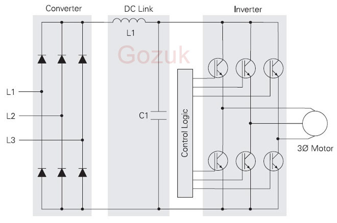
Variable frequency drive Rectifier
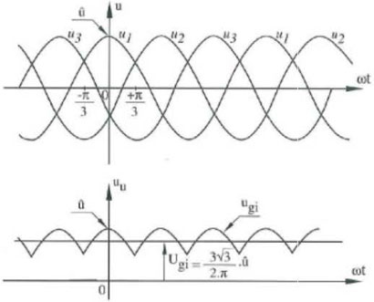 To understand variable frequency drive (VFD) better, it's necessary to explain some of the main parts of the variable frequency ...
 To understand variable frequency drive (VFD) better, it's necessary to explain some of the main parts of the variable frequency ...
VFD controlled Induction motor ...
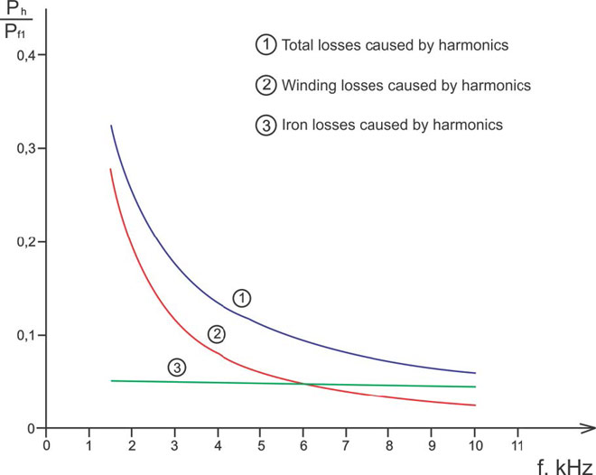 This paper presents a procedure to measure the efficiency on an induction motor fed by a VFD by the all operation range to speed ...
 This paper presents a procedure to measure the efficiency on an induction motor fed by a VFD by the all operation range to speed ...
VFD: Pulse Width Modulation (PWM)
 Pulse Width Modulation (PWM) VFDs provide a more sinusoidal current output to control frequency and voltage supplied to an AC ...
 Pulse Width Modulation (PWM) VFDs provide a more sinusoidal current output to control frequency and voltage supplied to an AC ...
Variable frequency drive Advantages & ...
VFDs are good for variable speed, in a water pump this is used to maintain a steady pressure, they will smooth out variances in ...
Variable frequency drive Energy saving
 Energy can be saved in a VFD by reducing the losses in the electric motor or by reducing the energy consumption of the variable ...
 Energy can be saved in a VFD by reducing the losses in the electric motor or by reducing the energy consumption of the variable ...
VFD manufacturers
