VFD wiring
1. Main circuit wiring
The VFD main circuit terminals shown as below Figure.
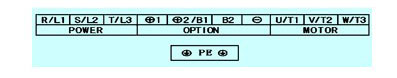
(1) The VFD's three phase AC input terminals (r/l1, s/l2, t/l3)
The power line's input terminals connect to 3 phase AC power through line protection or leakage protection breaker, it does not need to consider the connection of phase sequence. What needs to pay attention is the three-phase AC power must NOT be connected to the VFD drive output terminals directly, otherwise it will lead to the VFD's internal components damaged.
(2) The VFD 3-phase AC output terminal (C)
The electric motor should be connected to the output terminals by correct phase sequence, if the motor is in the reverse direction, then change any two phase of (u/t1, v/t2, w/t3), it also can be achieved by setting the VFD parameters. It should be noted that the output terminal can not connect the phase capacitor and surge absorber.
(3) DC reactor connection terminals (φ1, φ2/b1)
DC reactor connection terminals connect to the DC reactor to improve power factor with a short-circuit conductor connected to the terminals, when using the DC reactor, remove the short-circuit conductor first.
Note: Do NOT need to remove the conductor if the DC reactor is not connected.
(4) Brake unit connection terminals (φ2/b1, b2)
Generally small power VFD (1hp ~ 20hp) built-in braking resistor, while the 18.5kw and above need external braking resistor connection.
(5) DC power input terminals (φ1, θ)
The DC input terminals of the external brake unit are the positive and negative terminals of the DC bus.
(6) Ground terminal (PE)
The VFD will generate leakage current, the higher the carrier frequency, the larger the leakage current. The leakage current of the whole VFD is more than 3.5ma, the leakage current size is determined by the service conditions, in order to ensure safety, the variable frequency drive and electric motor must be grounded.
2. Precautions
(1) The grounding resistance should be less than 10 ω. The grounding cable diameter should be determined by the VFD power;
(2) Never share grounding wire with the welding machines and other power equipment;
(3) If the supply line is zero/earth wire shared, it is better to consider a separate laying for the earth wire;
(4) Multiple VFDs ground should be connected to the earth respectively, do not make the ground wire form a loop.
3. Control circuit terminals wiring
(1) As the low voltage VFD over-current of the control circuit cables is generally small, so the size of the control cable can be standardized, in order to avoid the interference caused by malfunction, the control cables should be twisted shielded wires;
(2) The control line and the main circuit cable laying
The VFD control lines should be laid separate from the main circuit cable and other power cable, and as far away as possible from the main circuit like more than 100mm; And don't parallel to the main circuit cable laying, do not cross the main circuit, if it must cross then it should be a vertical cross method.
(3) The cable shielding
The VFD cable shielding can adopt grounded metal tube or shielded cable. One end of Shielded layer connects to the VFD drive control circuit common (COM), but do not connect to the VFD ground end (e), the other end of the shield is vacant.
(4) The volume control switching line
The VFD switching control lines are allowed not to use the shielded wire, but two of the same signal lines must be twisted around each other, the twist pitch of the strands should be as small as possible, and the shielded layer connects to the ground terminal E of the VFD, the signal cable maximum length should not exceed 50m.
(5) Control circuit grounding
- the weak voltage/current loop wire connect to earth, and the grounding wire should not be used as the transmitted signal circuit;
- the wire's grounding should be in the VFD side, use a dedicated ground terminal and do not shared with other ground terminals.

MCCB (molded case circuit breaker)
Do not use a circuit breaker for start/stop operation. When a ground fault interrupter is used, select the one with no influence for high frequency. Setting current should be 200mA or above and the operating time at 0.1 second or longer to prevent malfunction.
MC (magnetic contactor)
It is not always necessary to have the MC on the input side. However, an input MC can be used to prevent an automatic restart after recovery from an external power loss during remote control operation. Do not use the MC for start/stop operation.
AC REACTOR
When power capacity is significantly large compared to inverter capacity, or when the power factor needs to be improved, externally connect an AC reactor. Many VFD manufacturers install reactors in the drives. It is always a good idea to check.
Input Noise Filter
To comply with certain communication and interference regulations, input noise filters are to be installed. Many manufacturers include these filters.
Variable Frequency Drive
Wire input to terminals L1, L2 and L3 for three phase input. Make sure to connect the ground terminal to an appropriate safety ground.
Output Noise Filter (EMI Suppression)
When used with output noise filter, radiated and conducted emissions may be reduced. dT/dV filters protect motors from EMI and voltage transients output from the drive itself. Not required if the motor is inverter rated.
Motor
When multiple motors are driven in parallel with an VFD, the VFD rated current should be at least 1.1 times the total motor rated current. Make sure that the motor and the variable frequency drives are separately grounded.
The VFD main circuit terminals shown as below Figure.
(1) The VFD's three phase AC input terminals (r/l1, s/l2, t/l3)
The power line's input terminals connect to 3 phase AC power through line protection or leakage protection breaker, it does not need to consider the connection of phase sequence. What needs to pay attention is the three-phase AC power must NOT be connected to the VFD drive output terminals directly, otherwise it will lead to the VFD's internal components damaged.
(2) The VFD 3-phase AC output terminal (C)
The electric motor should be connected to the output terminals by correct phase sequence, if the motor is in the reverse direction, then change any two phase of (u/t1, v/t2, w/t3), it also can be achieved by setting the VFD parameters. It should be noted that the output terminal can not connect the phase capacitor and surge absorber.
(3) DC reactor connection terminals (φ1, φ2/b1)
DC reactor connection terminals connect to the DC reactor to improve power factor with a short-circuit conductor connected to the terminals, when using the DC reactor, remove the short-circuit conductor first.
Note: Do NOT need to remove the conductor if the DC reactor is not connected.
(4) Brake unit connection terminals (φ2/b1, b2)
Generally small power VFD (1hp ~ 20hp) built-in braking resistor, while the 18.5kw and above need external braking resistor connection.
(5) DC power input terminals (φ1, θ)
The DC input terminals of the external brake unit are the positive and negative terminals of the DC bus.
(6) Ground terminal (PE)
The VFD will generate leakage current, the higher the carrier frequency, the larger the leakage current. The leakage current of the whole VFD is more than 3.5ma, the leakage current size is determined by the service conditions, in order to ensure safety, the variable frequency drive and electric motor must be grounded.
2. Precautions
(1) The grounding resistance should be less than 10 ω. The grounding cable diameter should be determined by the VFD power;
(2) Never share grounding wire with the welding machines and other power equipment;
(3) If the supply line is zero/earth wire shared, it is better to consider a separate laying for the earth wire;
(4) Multiple VFDs ground should be connected to the earth respectively, do not make the ground wire form a loop.
3. Control circuit terminals wiring
(1) As the low voltage VFD over-current of the control circuit cables is generally small, so the size of the control cable can be standardized, in order to avoid the interference caused by malfunction, the control cables should be twisted shielded wires;
(2) The control line and the main circuit cable laying
The VFD control lines should be laid separate from the main circuit cable and other power cable, and as far away as possible from the main circuit like more than 100mm; And don't parallel to the main circuit cable laying, do not cross the main circuit, if it must cross then it should be a vertical cross method.
(3) The cable shielding
The VFD cable shielding can adopt grounded metal tube or shielded cable. One end of Shielded layer connects to the VFD drive control circuit common (COM), but do not connect to the VFD ground end (e), the other end of the shield is vacant.
(4) The volume control switching line
The VFD switching control lines are allowed not to use the shielded wire, but two of the same signal lines must be twisted around each other, the twist pitch of the strands should be as small as possible, and the shielded layer connects to the ground terminal E of the VFD, the signal cable maximum length should not exceed 50m.
(5) Control circuit grounding
- the weak voltage/current loop wire connect to earth, and the grounding wire should not be used as the transmitted signal circuit;
- the wire's grounding should be in the VFD side, use a dedicated ground terminal and do not shared with other ground terminals.
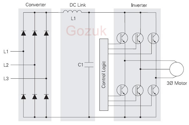
Variable Frequency Drive Wiring Accessories
MCCB (molded case circuit breaker)
Do not use a circuit breaker for start/stop operation. When a ground fault interrupter is used, select the one with no influence for high frequency. Setting current should be 200mA or above and the operating time at 0.1 second or longer to prevent malfunction.
MC (magnetic contactor)
It is not always necessary to have the MC on the input side. However, an input MC can be used to prevent an automatic restart after recovery from an external power loss during remote control operation. Do not use the MC for start/stop operation.
AC REACTOR
When power capacity is significantly large compared to inverter capacity, or when the power factor needs to be improved, externally connect an AC reactor. Many VFD manufacturers install reactors in the drives. It is always a good idea to check.
Input Noise Filter
To comply with certain communication and interference regulations, input noise filters are to be installed. Many manufacturers include these filters.
Variable Frequency Drive
Wire input to terminals L1, L2 and L3 for three phase input. Make sure to connect the ground terminal to an appropriate safety ground.
Output Noise Filter (EMI Suppression)
When used with output noise filter, radiated and conducted emissions may be reduced. dT/dV filters protect motors from EMI and voltage transients output from the drive itself. Not required if the motor is inverter rated.
Motor
When multiple motors are driven in parallel with an VFD, the VFD rated current should be at least 1.1 times the total motor rated current. Make sure that the motor and the variable frequency drives are separately grounded.
i want to know how much terminal used in vfd outgoing and incoming.
Post a Comment:
You may also like:
Featured Articles
Variable frequency drive Rectifier
 To understand variable frequency drive (VFD) better, it's necessary to explain some of the main parts of the variable frequency ...
To understand variable frequency drive (VFD) better, it's necessary to explain some of the main parts of the variable frequency ...VFD controlled Induction motor ...
 This paper presents a procedure to measure the efficiency on an induction motor fed by a VFD by the all operation range to speed ...
This paper presents a procedure to measure the efficiency on an induction motor fed by a VFD by the all operation range to speed ...VFD: Pulse Width Modulation (PWM)
 Pulse Width Modulation (PWM) VFDs provide a more sinusoidal current output to control frequency and voltage supplied to an AC ...
Pulse Width Modulation (PWM) VFDs provide a more sinusoidal current output to control frequency and voltage supplied to an AC ...What is VFD, How it works? - VFD ...
 VFD is shorted for Variable Frequency Drive (also known as AC Drives and Inverters) -- that's used to make an AC motor working in ...
VFD is shorted for Variable Frequency Drive (also known as AC Drives and Inverters) -- that's used to make an AC motor working in ...Variable frequency drive Advantages & ...
VFDs are good for variable speed, in a water pump this is used to maintain a steady pressure, they will smooth out variances in ...

VFD manufacturers