VFD with Variable Voltage Input
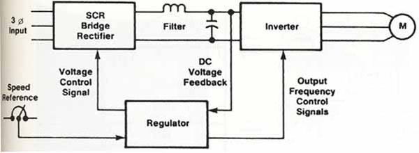
The variable voltage input (VVI) VFD is the technology that was used in some of the earliest VFD. Since these earlier VFDs did not have microprocessor chips to establish the transistor VFDs signals, they used existing technology such as oscillators. The diagrams below shows a block diagram of this type of VFD and a typical waveform of the output.

From the block diagram one can see that the basic parts of the VFD such as the rectifier section, filter and inverter sections are much the same as modern VFDs. The major difference is that SCRs are used for the rectifier section instead of diodes. The reason for this is that diodes were not manufactured as large as SCRs at this time, so the SCRs were used because they were more durable. It is also possible to adjust the SCR's timing with a signal from the regulator section of the VFD to change the amount of voltage and current delivered to the VFD. The amount provided sufficient change to meet most of the varying demands of torque.
From the waveform diagram you can see that the voltage waveform was a six-step signal. The switching device in the inverter section would be switched on and off at specific points to provide the six-step signal. The current waveform looks more like a sine wave because the inductance of the motor helps to cause the phase shift needed to smooth out the square wave shape of the six-step signal. You will encounter a few VFDs with this early technology because they have paid for themselves over and over. In some cases the VFDs are changed and a newer microprocessor programmable VFD is used whenever there is a problem with the original VFD. It is also more practical to change to a modern VFD that can provide a wider range of torque for all applications the motor may encounter.
Post a Comment:
You may also like:
Featured Articles
What is VFD, How it works? - VFD ...
 VFD is shorted for Variable Frequency Drive (also known as AC Drives and Inverters) -- that's used to make an AC motor working in ...
 VFD is shorted for Variable Frequency Drive (also known as AC Drives and Inverters) -- that's used to make an AC motor working in ...
VFD: Insulated Gate Bipolar Transistor ...
 IGBT (insulated gate bipolar transistor) provides a high switching speed necessary for PWM VFD operation. IGBTs are capable of ...
 IGBT (insulated gate bipolar transistor) provides a high switching speed necessary for PWM VFD operation. IGBTs are capable of ...
Three phase inverters
 In the variable frequency drive rectifier paper, it explains how to go from three phase alternating current voltage to a direct ...
 In the variable frequency drive rectifier paper, it explains how to go from three phase alternating current voltage to a direct ...
Variable Frequency Drive Harmonics and ...
A discussion of the benefits of variable frequency drives often leads to a question regarding electrical harmonic distortion ...
Variable frequency drive Energy saving
 Energy can be saved in a VFD by reducing the losses in the electric motor or by reducing the energy consumption of the variable ...
 Energy can be saved in a VFD by reducing the losses in the electric motor or by reducing the energy consumption of the variable ...
VFD manufacturers
