Home » Applications » Page 2
VFD technology is not new to the HVAC industry. Variable frequency drives have been used extensively for air handling unit fans, cooling tower fans and water pumps for a long time. With state-of-the-art compressor technology and microprocessor based control systems, manufacturers now offer variable frequency drives specially designed for centrifugal chillers.
In the real world, energy performance at real world conditions has little to do with bottom line energy costs - what happens at off design conditions is much more important. Even with a relatively warm temperature in China, VFD energy savings of $0.94 Million were possible when compared to a fixed speed drive or even for that matter any positive displacement compressor like a screw chiller. This makes an excellent opportunity to attain quick payback and return on the VFD investment, particularly for facilities operating continuously such as hotels, hospitals, call centers, software centers and factories.
VFD on centrifugal chillers is being used by most of the major centrifugal suppliers as new equipment offering or retrofit option. Considering the ever increasing cost of electricity ,it's a wiser choice to opt for energy saving options like VFD on centrifugal chillers.
Many special software functions are available in the VFD for optimum crane operations. These facilitate performance monitoring in field weakening operation (higher speed at partial load), load spectrum calculation or speed monitoring, for example. The variable frequency drive can be connected to the existing joystick controller of cranes fitted with cab controls. Programmable characteristic curves make the VFD possible to adapt operation perfectly to meet the specific requirements of the handling application.
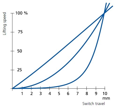
(The characteristic curve to operate the joystick is freely programmable.)
An intelligent brake logic system in the VFD enables the brake function to be monitored by evaluating the signals from the corresponding feedback contacts. Torque pre-control at start-up also enables heavy loads to be handled more precisely by hoist units. The VFD system bus (fibre optic cable) for Master/Slave applications is suitable for implementing electronic gearboxes by synchronizing two hoists for transporting long materials. Furthermore, the Master/Follower function makes VFD possible to share the load/torque between two mechanically connected geared motors on one hoist unit.
In cement plants, VFDs provide controlled torque and speed to the kiln, which increases the life of the mechanical system, and reduces maintenance and operating costs. The VFDs also provide feedback signals, which improve cement kiln process control.
Gozuk provides both ac and dc drive technology suitable for cement kiln applications. In the past, dc drives and motors have been the VFD systems of choice for cement kiln industries. With the rapid advance of power semiconductors and ac VFD controls, ac VFDs have gained acceptance for cement kilns in recent years. A tremendous amount of effort has also been put into developing the advanced diagnostic features, which work to greatly reduce downtime and troubleshooting time.
Gozuk provides both ac and dc drive technology suitable for cement kiln applications. In the past, dc drives and motors have been the VFD systems of choice for cement kiln industries. With the rapid advance of power semiconductors and ac VFD controls, ac VFDs have gained acceptance for cement kilns in recent years. A tremendous amount of effort has also been put into developing the advanced diagnostic features, which work to greatly reduce downtime and troubleshooting time.
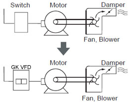
Air handling equipment consumes enormous quantities of energy, and deserves some thoughtful consideration by those who manage profits and, therefore, desire to save more money through energy management. The purpose of this cost justification guide is to provide a practical tool for management so that an estimate of VFD annual savings can be made. Unlike a computer generated payback analysis, this guide allows the user to see where the numbers come from and how the VFD stacks up against other flow control methods.
VFDs are widely used to control the speed of conveyor systems, blower speeds, pump speeds, machine tool speeds, & other applications that require variable speed with variable torque. In some applications such as speed control for a conveyor, the VFD is installed with a remote potentiometer that personnel can adjust manually to set the speed for the conveyor. In this type of application, the personnel who use the conveyor can manually set the motor speed with the minimum & maximum frequency that is programmed into the VFD parameters.
The application for the VFD below is enabled and controlled by external switches or contacts. The National Electric Code (NEC) and local codes will specify the exact number of external controls required for each VFD. The block diagram for the VFD below shows typical control switches. You can note that at the upper left side of the VFD that a NO (normally open) start push-button is connected to terminals TB2-7 and TB2-6, and an NC (normally closed) stop button is connected between terminals TB2-7 and TB2-8. The voltage for these circuits is provided internally from TB2-7. Power must be received continually through the stop push-button, and when the start push-button is depressed a pulse signal will be received and the VFD's start sequence will begin. The start sequence will provide a ramp that's used to start the motor by slowly increasing the frequency and voltage. Anytime the stop button is opened, the VFD will be stopped and if a ramp-down sequence is programmed, the VFD will come to a gradual stop. If a ramp-down sequence is not programmed, the motor can be stopped with braking, or it can be allowed to coast to a stop.

The second set of switches provides a set of terminals where an external set of contacts from a control relay can be connected to provide a VFD-enable function. When the contacts are connected to terminals TB2-11 and TB2-12, power will flow from terminal TB2-12 through the closed contacts to terminal TB2-11 to enable the VFD. When the VFD is in the enable condition, power is allowed to flow through the drive motor. Anytime these contacts are opened, the VFD will become disabled, and the VFD will not send voltage to the motor.
The second set of switches provides a set of terminals where an external set of contacts from a control relay can be connected to provide a VFD-enable function. When the contacts are connected to terminals TB2-11 and TB2-12, power will flow from terminal TB2-12 through the closed contacts to terminal TB2-11 to enable the VFD. When the VFD is in the enable condition, power is allowed to flow through the drive motor. Anytime these contacts are opened, the VFD will become disabled, and the VFD will not send voltage to the motor.
Variable frequency drive on HVAC Chiller
Installation of a variable frequency drive on an existing chiller.
Installation of a variable frequency drive on an existing chiller.
- Installation of the variable frequency drive must accompany the permanent removal or disabling of existing flow control devices.
- New chillers with integrated variable frequency drives may be eligible under the Air-Cooled and Water-Cooled Chiller incentive.
- variable frequency drives installed on new equipment are not eligible for this incentive.
Tags: VFD installation
The system composition diagram is shown as FIG. 1:
The variable frequency circuit includes: knife switch, breaker, VFD, contactor under the VFD and energy feedback unit, which, the energy feedback unit composes one cabinet.
Control circuit: consists of main PLC, auxiliary PLC, touch screen, relay auxiliary control and operation panel. The main PLC and auxiliary PLC compensate each other, the relay auxiliary control, main PLC control and auxiliary PLC control are installed in the same control cabinet, and the touch screen is installed on the operation panel as the upper computer. As the feedback signal of location and speed, the encoder is installed in the motor and hoisting drum. The speed-measuring encoder installed in the motor feeds back the signal to the VFD, which constitutes a PG vector control; another encoder feeds back a signal to the PLC to calculate the speed and location. The signals of the speed-measuring motor, oil temperature, oil pressure and other switching values enter the PLC system.
Featured Articles
Variable frequency drive application ...
 Variable Frequency Drive (VFD) can be used in lots of fields. Variable frequency drives are widely used to control the speed of ...
Variable Frequency Drive (VFD) can be used in lots of fields. Variable frequency drives are widely used to control the speed of ...
VFD manufacturers