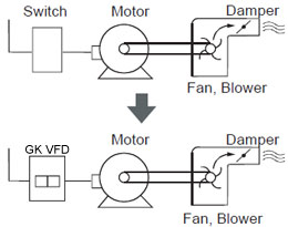
Basic differences in winding characteristics of a motor for VFD and DOL
The basic consideration is how close the variable frequency drive (VFD) output waveform approximates a true sinusoid. Most modern VFDs produce reasonable approximations - if viewed from a "macro" perspective. But when we zoom in to specific instances and pulses, we see there is always some amount of voltage over/undershoot occurring. And VFDs which contain an intermediate DC bus (which is pretty much a given, if the input and output are AC at different frequencies) will often have what is called a "common mode" voltage. This tends to elevate the neutral plane (on the motor side) by some amount - resulting in additional stress on the motor winding insulation.

Anything which distorts the waveform from a true sinusoid - and a true neutral - will negatively impact the insulation system through increased heating or voltage stress. Either way, the motor system has to accommodate the VFD output - so the system is designed differently.
For protection against harmonics injected by VFD, the dielectric strength of the winding has to be strengthened. This is done by using VPI treatment. If the motor is wire wound (mostly for up to 690 V design), dual enamel coated winding wire is recommended for extra winding strength. Also note that due to impure supply (i.e. harmonics) from VFD, additional heat losses are generated in winding and if the motor is to be operated near about 100% loading, temp. Rise may cross limit of class B, that is 120 deg. C. For this reason, class H winding insulation is recommended for longer motor life for constant torque application.
Also, higher shaft voltage may incur due to VFD supply which can damage bearings which may also result into winding failure. To prevent this, insulated bearing at motor non-drive end must be used for higher frame motors (usually IEC frame 315 and above) in wire wound. For strip wound motors (for 3.3 kV onwards), insulated non-drive end shield is used instead of insulated bearing.
Also, if is it constant torque application and minimum motor speed on VFD supply is less than 50% of the rated speed, better to go with forces cooling (IC 416 / IC 616 / IC 666 / IC 86W).
great featured article. Great comparison of vfd and dol winding.
Post a Comment:
You may also like:
Featured Articles
Non-Enclosure Variable Frequency Drive ...
 No enclosure (cover), reducing installation space and cost effective. Widely used in All-In-One control cabinet. Keep the same ...
No enclosure (cover), reducing installation space and cost effective. Widely used in All-In-One control cabinet. Keep the same ...Variable frequency drive application ...
 Variable Frequency Drive (VFD) can be used in lots of fields. Variable frequency drives are widely used to control the speed of ...
Variable Frequency Drive (VFD) can be used in lots of fields. Variable frequency drives are widely used to control the speed of ...Variable frequency drive in HVAC ...
 Variable frequency drives (VFD) have been used for HVAC systems in buildings for more than 40 years. But only in recent years, ...
Variable frequency drives (VFD) have been used for HVAC systems in buildings for more than 40 years. But only in recent years, ...Variable Frequency Drive Harmonics and ...
A discussion of the benefits of variable frequency drives often leads to a question regarding electrical harmonic distortion ...
Three phase inverters
 In the variable frequency drive rectifier paper, it explains how to go from three phase alternating current voltage to a direct ...
In the variable frequency drive rectifier paper, it explains how to go from three phase alternating current voltage to a direct ...
VFD manufacturers