Home » Troubleshooting » Problems caused by Variable frequency drives
Problems caused by Variable frequency drives
Leaving aside for the moment the whole climate change debate, there is no doubt that industry in general would benefit by reducing its consumption of energy. The chemical industry in particular has rightly put energy efficiency and conservation at the top of its agenda, with many plants paying increasing attention to ways of better managing their energy usage. Further opportunities certainly exist, as underscored by the recent launch by the U.S. Dept. of Energy (DOE) of its Save Energy Now initiative that targets major chemical plants, among other large industrial facilities.
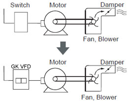
One move that has already found support across the broad spectrum of operators, suppliers, government agencies and industry bodies is the use of VFDs. These VFDs can be used to run a plants AC motors, which previously might have been operated at constant speed all the time. With the DOE estimating that some 18% of the energy consumed by the nations industrial motors could be saved by switching to energy efficient technologies, such as variable frequency drives, it would seem to be an open and shut case in their favor. And, so it has proved in most applications. Occasionally, though, running an AC motor off a variable frequency drive can lead to problems that many a process engineer might not have come across before.
A tip-off
We started to pick up on VFD problems through a service we offer that analyzes field failures, says Dan Snyder, director of applications engineering with SKF USA, Kulpsville, Pa., about a series of bearing noise and grease failure problems that were being reported back to the bearing manufacturer some years ago. The VFD problems seemed directly related to some sort of electrical discharge through the bearing that, says Snyder, manifested itself as possible arcing across the lubrication gap.
Although the arcing tends to be isolated and localized, the effect on the bearing is almost like a series of little lightning strikes, he says. These strikes melt and retemper the internal bearing surfaces where the discharges occur, with the result that some surface material flakes away and spalls out to create noise in the bearing.
The first symptoms, however, are virtually invisible to the naked eye. The damaged surface appears dull, characterized by molten pit marks or microcraters that may be only around 5 to 8 μm in diameter, irrespective of whether they are on the inner ring, outer ring or a rolling element.
Initially, such damage now known as the electric discharge machining (EDM) effect was put down to the likelihood of stray currents from, for example, inadequately grounded welding work being carried out on the motor or VFD. But then more recently, says Snyder, we started seeing the problem more and more on AC motors that had been fitted with VFDs for variable speed control. And the higher the frequency, the more bearing damage we were seeing.
The typical type of VFD damage only really shows up when characteristic bearing fluting becomes visible. This is caused by the dynamic effect of the rolling elements continually going over the microcraters and etching a rhythmic pattern into the running surfaces of the bearings races. Noise and vibration from the bearing increases, and eventually the deterioration will lead to complete bearing failure.
Even if the bearing itself is not affected by these discharges, its lubrication could be. The grease composition can degrade rapidly under the effect of current discharges, with the high localized temperatures generated causing the lubricants additives and base oils to react, with burning or charring of the oil.
The cause
At the root of all these problems, according to Geoff Brown, VFDs application consultant with motor and VFD manufacturer ABB, New Berlin, Wisc., is what is known as common mode voltage. Under normal conditions, a typical three-phase sinusoidal power supply is balanced and symmetrical the vector sum of the three phases is always equal to zero, with the neutral at zero volts. Variable frequency drives, however, work by converting that sinusoidal line AC voltage to DC, then back to a pulse-width-modulated (PWM) AC voltage of variable frequency, by which the motor speed can be controlled. The switching frequency of these pulses can range from 1 kHz to 20 kHz and, while the voltages may be balanced in peak amplitude, this variation makes it impossible to achieve perfect balance between the phases instantaneously. When this happens, the neutral is no longer zero but at what can be defined as a common mode voltage.
VFD common mode voltage induces current in the motor shaft, explains Brown, and it is this common mode current that causes the problem. Again, it is not a new problem. Brown harks back to the early days of offshore oil and gas production rigs in the North Sea, where large 3.3-kV VFD systems generally were not grounded and the problem of stray currents became something of a cause source. Basically, he says, it was found that if you didn't have a balanced supply then you would end with circulating currents.
That variable frequency drives can cause circulating currents has clearly been known for some time, but the problem seems to have become exacerbated by the very improvements that have made variable frequency drives increasingly popular namely, the fast-switching insulated gate bipolar transistor (IGBT) technology commonly employed in the VFDs. As Browns colleague, Matti Laitinen, VFDs design manager of ABB Industry Oy, Helsinki, Finland, explained: Fast rising voltage pulses produced by modern power supplies contain high frequencies that initiate high frequency currents which will flow through stray capacitances in the motor system. Such currents are part of the total common mode current, and follow a path called the common mode loop. Several such loops can be formed in any VFD system, depending on the VFD system architecture and the installation techniques used, but they all start at the source of the common mode voltage, the inverter itself. Here the fluctuating potential of the VFD DC bus produces large current flows at very high pulse frequencies, and these currents will seek the path of least resistance to return to the bus via the windings, the shaft and, if they are not stopped or diverted, via the bearings themselves.
One cure
So how can you prevent these stray currents from chewing up your motor bearings? The simplest, though not necessarily the cheapest, way is to stop them flowing through the bearings in the first place. In other words, insulate the bearings from the shaft currents. This is the option offered by SKF, as Snyder explains: We have two solutions: one is to put a ceramic coating on the OD [outside diameter] of the bearing, which provides a resistance to any current trying to go through it, while the other way is to actually replace the rolling elements within the bearing with ceramic balls or rollers the same effect, really, but all the insulating material is contained within the bearing instead of being on the outside.
The first solution comprises the Insocoat range. These bearings, in all common sizes above 70-mm bore diameter, are coated either on the outer or inner ring with a nominal 100-μm-thick aluminum oxide layer that is applied using a plasma spraying technique. The standard layer thickness is said to prevent most current passage problems.
SKFs other option is its Hybrid design. These bearings combine silicon nitride ceramic rolling elements with steel rings. The result is a lighter, harder and more durable alternative to conventional all-steel bearings, capable of running at higher speeds and lower operating temperatures. And the natural insulating properties of the ceramic elements is said to make them ideal for large variable-speed motors. Standard types include single row, deep groove ball bearings with bore diameters from 5 mm to 110 mm, although SKF can customize hybrids to meet specific application requirements.
We can work with the end users to try and solve their problems, says Snyder, and then we will take that knowledge and experience back to the original equipment manufacturer (OEM) to provide a value-added product for them to put in their motors but thats a tougher sell unless you can get the pull-through from the end user.
Right now, users are not doing much pulling because motor manufacturers generally have not exactly been shouting about the possible bearing problems associated with variable frequency drive, notes Snyder. Weve had the products [Insocoat and Hybrid] on the market for six years now, but theyve only recently been gaining momentum as more people are beginning to recognize the problem. We probably saw it before [the OEMs] because we were seeing bearings come back to us. Sometimes we would recognize the problem before the customer, who just looked upon it as bearing failure without appreciating the root cause. And the OEMs weren't really seeing the problems either, because the motors were going through rebuild shops and the feedback loop to the OEMs wasnt quite what it is now.
Its often said that for every problem there is a solution, but for this solution insulated bearings there can also be a problem. The VFD common mode currents may well be prevented from flowing through the bearings, but they have to go somewhere. This is why ABBs Brown says that insulated bearings should only be fitted to one end (the non-driven one) of the motor VFD shaft. (ABB offers insulated bearings as a standard option on motors above 280 frame size, but doesn't fit them if the motor is to be used at constant speed.) Fitting such bearings at both ends of the shaft can cause problems as the stray currents can go into the driven device. We have seen examples of pump impellers being eroded in this way.
Another option
John Malinowski of Baldor Electric in Fort Smith, Ark., makes a similar point: We know a lot more about this phenomenon [stray shaft currents] today than in the past and can reduce its occurrence as long as correct VFD installation, setup and wiring practices are followed. Obviously, there may be rare occasions where the fluting still occurs, or where the user wants to ensure he has no problems by building in a safety margin. This is when shaft grounding and isolated bearings may be used. Either may be retrofitted, but with the bearings the motor shaft must be insulated from the load so it doesn't transfer the current into the driven load bearings.
Gozuk recommends the use of shaft grounding brushes as the simplest and most cost-effective way of dealing with the problem. It offers a grounding brush as standard on its 250-hp and larger VFD or Vector VFD motors, which are specifically designed to be powered from variable frequency drives.
Operating on a similar principle is the recently introduced Motor Grounding Seal (MGS) from Inpro/Seal of Rock Island, Ill. An alternative to insulated bearings is to provide a path to ground for the shaft currents before they can get to the bearings. This is the principle behind the Motor Grounding Seal (MGS), recently introduced by Inpro/Seal of Rock Island, Ill. Developed in conjunction with Electro Static Technology (EST) of Mechanical Falls, Maine, the MGS essentially is a bearing isolator, or labyrinth seal, that includes a built-in grounding ring and brush from EST. The brush contains microfibers that completely surround the shaft to discharge any current flowing through it.
ESTs version of the same device has been dubbed the Aegis shaft grounding coupling (SGC) and, according to EST general manager Tony King, is the first product of its kind to provide a solution to two significant industry challenges shaft current elimination and bearing isolation while delivering a maintenance-free and cost-effective solution that is truly revolutionary and makes all other technologies obsolete. These are bold claims indeed to make to an industry that looks upon brush-based electrical connections as anything but maintenance free.
At the core of Aegis is ESTs patent-pending Electron Transport Technology, which the company says effectively creates an ultra-low resistance path between the motor shaft and frame to dissipate all of the damaging shaft current to ground. Aegis solves the problem, says engineering manager Willam Oh, by providing a virtual short between shaft and frame so that shaft voltages and currents cannot build up in the first place.
Good advice
Clearly, there is a potential problem surrounding the use of variable frequency drives, but most observers agree that it is still relative rare and unpredictable, albeit becoming more visible simply because of the growing number of variable frequency drives in operation. The advice given some time ago by David Kowal, almost certainly still holds good today: Bearing damage resulting from EDM doesn't have to be chronic or remain unexplained. Understanding what voltage sources result in and which machines are more susceptible to EDM damage, knowing what questions to ask, knowing how to identify EDM damage through visual inspection and vibration data, and acquiring shaft-to-ground voltage and current readings can assist in combating this phenomena.
Post a Comment:
You may also like:
Featured Articles
Non-Enclosure Variable Frequency Drive ...
 No enclosure (cover), reducing installation space and cost effective. Widely used in All-In-One control cabinet. Keep the same ...
No enclosure (cover), reducing installation space and cost effective. Widely used in All-In-One control cabinet. Keep the same ...Variable frequency drive application ...
 Variable Frequency Drive (VFD) can be used in lots of fields. Variable frequency drives are widely used to control the speed of ...
Variable Frequency Drive (VFD) can be used in lots of fields. Variable frequency drives are widely used to control the speed of ...Variable frequency drive in HVAC ...
 Variable frequency drives (VFD) have been used for HVAC systems in buildings for more than 40 years. But only in recent years, ...
Variable frequency drives (VFD) have been used for HVAC systems in buildings for more than 40 years. But only in recent years, ...Variable Frequency Drive Harmonics and ...
A discussion of the benefits of variable frequency drives often leads to a question regarding electrical harmonic distortion ...
Three phase inverters
 In the variable frequency drive rectifier paper, it explains how to go from three phase alternating current voltage to a direct ...
In the variable frequency drive rectifier paper, it explains how to go from three phase alternating current voltage to a direct ...
VFD manufacturers
A grounding ring is only as good as the impedance of it. At many mega hertz that impedance is very high, so a VFD circuit with let's say a .10 Ohm impedance makes mince meat out of a ring with 1 Ohm. The only thing a ring is good for is to discharge any static charges. It will have very little effect on a VFD generated signal.
I will be glad to demonstrate the measurements to whomever is interested in this. And by the way, any VFD, size does not matter, will generate both the common mode and the differential mode signals.
The differential mode signal will eventually destroy the insulation in a motor, if not treated properly. Any one who has taken a motor apart after it failed insulation happened, will notice a white powder in the failed area. This is a product of the fast rising impulse causing ionization, ionization causes ozone and ozone causes chlorine deficiency in the insulation product and ultimately failure.
The only way to prevent this is to convert the PWM signal to a sine wave, Period.