What is VFD, How it works? - VFD working principle
VFD is shorted for Variable Frequency Drive (also known as AC Drives and Inverters) -- that's used to make an AC motor working in variable speed (among other parameters). This is definition used in all topical discussion on this paper. A basic VFD system generally consists of an AC motor, a controller, and an operator interface.
VFD for AC motors have been the innovation that has brought the use of AC motors back into prominence. The AC-induction motor can have its speed changed by changing the frequency of the voltage used to power it. This means that if the voltage applied to an AC motor is 50 Hz (used in countries like China), the motor works at its rated speed. If the frequency is increased above 50 Hz, the motor will run faster than its rated speed, and if the frequency of the supply voltage is less than 50 Hz, the motor will run slower than its rated speed. According to the variable frequency drive working principle, it's the electronic controller specifically designed to change the frequency of voltage supplied to the induction motor.
In the 1960s, VFDs had rather small solid-state components that limited the amount of current the VFD could supply to the motor. This usually limited the size of the motor that could be controlled by a frequency and they were not commonly used. When larger transistors became available in the 1980s, VFDs allowed the largest motors to have their speed controlled. The earliest VFDs used linear amplifiers to control all aspects of the VFD. Jumpers and dip switches were used provide ramp-up (acceleration) and ramp-down (deceleration) features by switching larger or smaller resistors into circuits with capacitors to create different slopes.
The arrival of advanced microprocessors has allowed the VFD works as an extremely versatile device that not only controls the speed of the motor, but protects against overcurrent during ramp-up and ramp-down conditions. Newer VFDs also provide methods of braking, power boost during ramp-up, and a variety of controls during ramp-down. The biggest savings that the VFD provides is that it can ensure that the motor doesn't pull excessive current when it starts, so the overall demand factor for the entire factory can be controlled to keep the utility bill as low as possible. This feature alone can provide payback in excess of the price of the VFD in less than one year after purchase. It is important to remember that with a traditional motor starter, they will draw locked-rotor amperage (LRA) when they are starting. When the locked-rotor amperage occurs across many motors in a manufacturing plant, it pushes the electrical demand too high which often results in the plant paying a penalty for all of the electricity consumed during the billing period. Since the penalty may be as much as 15% to 25%, the savings on a $30,000/month electric bill can be used to justify the purchase VFDs for virtually every motor in the plant even if the application may not require working at variable speed.
Today the VFD is perhaps the most common type of output or load for a control system. As applications become more complex the VFD has the ability to control the speed of the motor, the direction the motor shaft is turning, the torque the motor provides to a load and any other motor parameter that can be sensed. Newer VFDs have a variety of parameters that can be controlled by numbers programmed into it or downloaded from another microprocessor-controlled system such as a programmable controller (PLC). These VFDs are also available in smaller sizes that are cost-efficient and take up less space.
The block diagram of a typical VFD can be divided into three major sections:
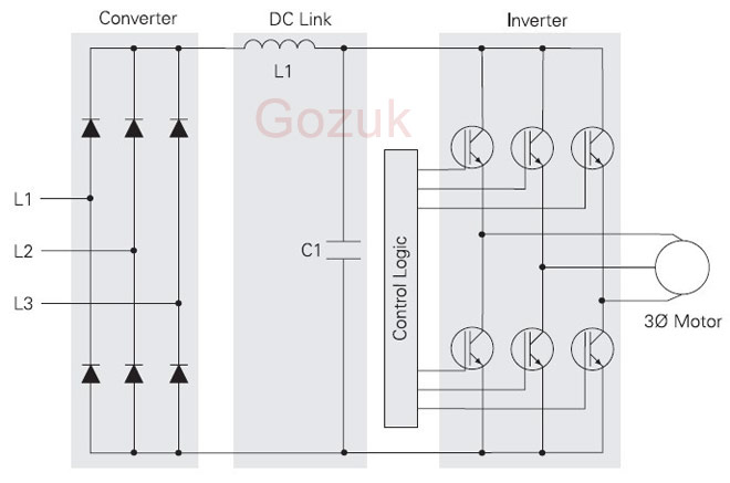
The block diagram below contains three separate sections to indicate the basic working principle of a VFD:

Above: The VFD shown as three separate sections: rectifier (where AC is converted to DC); the DC intermediate circuit which contains the capacitor and inductor for filtering. The third section is the DC-to-AC inverter where DC is turned back to three-phase AC.
VFD connect to standard AC induction motors, and have capabilities of adjustable speed, torque, and horsepower control similar to the principles of DC drives. VFDs have made AC squirrel cage induction motors as controllable and efficient as their DC counterparts. AC induction motor speed depends on the number of motor poles and the frequency of the applied power. The number of poles on the stator of the motor could be increased or decreased, but this has limited usefulness. Although the AC frequency of the power source in the China is fixed at 50 Hz, advances in power electronics make it practical to vary the frequency and make the induction motor working at different speed.
Three phase motors are usually preferred, but some types of single phase motors can be used with single phase variable frequency drives. Motors that are designed for fixed-speed main voltage operation are often used, but certain enhancements to the standard motor works offer higher reliability and better performance. A simplified VFD working principle diagram is shown in below. The three major sections of the controller are as follows: Converter-Rectifies the incoming three-phase AC power and converts it to DC.

DC filter (also known as the DC link or DC bus) - Provides a smooth, rectified DC voltage.
Inverter - The basic working principle of an inverter is switching the DC on and off so rapidly that the motor receives a pulsating voltage that is similar to AC. The switching rate is controlled to vary the frequency of the simulated AC that is applied to the motor.
AC motor characteristics require the applied voltage to be proportionally adjusted by the VFD whenever the frequency is changed. E.g., if a motor is designed to operate at 460 Volts at 60 Hz, the applied voltage must be reduced to 230 Volts when the frequency is reduced to 30 Hz. Thus the ratio of volts per hertz must be regulated to a constant value (460/60 = 7.67 in this case). The most common method used for adjusting the motor voltage is called pulse width modulation (PWM). With PWM voltage control, the inverter switches are used to divide the simulated sine-wave output waveform into a series of narrow voltage pulses and modulate the width of the pulses.
With a standard AC across-the-line motor starter, line voltage and frequency are applied to the motor and the speed is solely dependent on the number of motor stator poles. In comparison, a VFD delivers a varying voltage and frequency to the motor, which determines its speed. The higher the frequency sup plied to the motor, the faster it will run. Power applied to the motor through the VFD can make the motor working speed lower than the nameplate base speed, or increase the speed to synchronous speed and higher. Motor manufacturers list the maximum speed at which their motors can safely be worked.
VFD for AC motors have been the innovation that has brought the use of AC motors back into prominence. The AC-induction motor can have its speed changed by changing the frequency of the voltage used to power it. This means that if the voltage applied to an AC motor is 50 Hz (used in countries like China), the motor works at its rated speed. If the frequency is increased above 50 Hz, the motor will run faster than its rated speed, and if the frequency of the supply voltage is less than 50 Hz, the motor will run slower than its rated speed. According to the variable frequency drive working principle, it's the electronic controller specifically designed to change the frequency of voltage supplied to the induction motor.
In the 1960s, VFDs had rather small solid-state components that limited the amount of current the VFD could supply to the motor. This usually limited the size of the motor that could be controlled by a frequency and they were not commonly used. When larger transistors became available in the 1980s, VFDs allowed the largest motors to have their speed controlled. The earliest VFDs used linear amplifiers to control all aspects of the VFD. Jumpers and dip switches were used provide ramp-up (acceleration) and ramp-down (deceleration) features by switching larger or smaller resistors into circuits with capacitors to create different slopes.
The arrival of advanced microprocessors has allowed the VFD works as an extremely versatile device that not only controls the speed of the motor, but protects against overcurrent during ramp-up and ramp-down conditions. Newer VFDs also provide methods of braking, power boost during ramp-up, and a variety of controls during ramp-down. The biggest savings that the VFD provides is that it can ensure that the motor doesn't pull excessive current when it starts, so the overall demand factor for the entire factory can be controlled to keep the utility bill as low as possible. This feature alone can provide payback in excess of the price of the VFD in less than one year after purchase. It is important to remember that with a traditional motor starter, they will draw locked-rotor amperage (LRA) when they are starting. When the locked-rotor amperage occurs across many motors in a manufacturing plant, it pushes the electrical demand too high which often results in the plant paying a penalty for all of the electricity consumed during the billing period. Since the penalty may be as much as 15% to 25%, the savings on a $30,000/month electric bill can be used to justify the purchase VFDs for virtually every motor in the plant even if the application may not require working at variable speed.
Today the VFD is perhaps the most common type of output or load for a control system. As applications become more complex the VFD has the ability to control the speed of the motor, the direction the motor shaft is turning, the torque the motor provides to a load and any other motor parameter that can be sensed. Newer VFDs have a variety of parameters that can be controlled by numbers programmed into it or downloaded from another microprocessor-controlled system such as a programmable controller (PLC). These VFDs are also available in smaller sizes that are cost-efficient and take up less space.
The block diagram of a typical VFD can be divided into three major sections:
- the power-conversion section
- the microprocessor control section (CPU) and the control section that includes the external switches an signals to control the VFD operations
- the power section where AC voltage is converted to DC and then DC is inverted back to 3-phase AC voltage
The block diagram below contains three separate sections to indicate the basic working principle of a VFD:
- the rectifier
- the filter
- the switching section that uses regular transistors, darlington pair transistors, or insulated gate bipolar transistors (IGBT) to invert the DC voltage back to AC voltage with the proper frequency.
Above: The VFD shown as three separate sections: rectifier (where AC is converted to DC); the DC intermediate circuit which contains the capacitor and inductor for filtering. The third section is the DC-to-AC inverter where DC is turned back to three-phase AC.
VFD connect to standard AC induction motors, and have capabilities of adjustable speed, torque, and horsepower control similar to the principles of DC drives. VFDs have made AC squirrel cage induction motors as controllable and efficient as their DC counterparts. AC induction motor speed depends on the number of motor poles and the frequency of the applied power. The number of poles on the stator of the motor could be increased or decreased, but this has limited usefulness. Although the AC frequency of the power source in the China is fixed at 50 Hz, advances in power electronics make it practical to vary the frequency and make the induction motor working at different speed.
Three phase motors are usually preferred, but some types of single phase motors can be used with single phase variable frequency drives. Motors that are designed for fixed-speed main voltage operation are often used, but certain enhancements to the standard motor works offer higher reliability and better performance. A simplified VFD working principle diagram is shown in below. The three major sections of the controller are as follows: Converter-Rectifies the incoming three-phase AC power and converts it to DC.
DC filter (also known as the DC link or DC bus) - Provides a smooth, rectified DC voltage.
Inverter - The basic working principle of an inverter is switching the DC on and off so rapidly that the motor receives a pulsating voltage that is similar to AC. The switching rate is controlled to vary the frequency of the simulated AC that is applied to the motor.
AC motor characteristics require the applied voltage to be proportionally adjusted by the VFD whenever the frequency is changed. E.g., if a motor is designed to operate at 460 Volts at 60 Hz, the applied voltage must be reduced to 230 Volts when the frequency is reduced to 30 Hz. Thus the ratio of volts per hertz must be regulated to a constant value (460/60 = 7.67 in this case). The most common method used for adjusting the motor voltage is called pulse width modulation (PWM). With PWM voltage control, the inverter switches are used to divide the simulated sine-wave output waveform into a series of narrow voltage pulses and modulate the width of the pulses.
With a standard AC across-the-line motor starter, line voltage and frequency are applied to the motor and the speed is solely dependent on the number of motor stator poles. In comparison, a VFD delivers a varying voltage and frequency to the motor, which determines its speed. The higher the frequency sup plied to the motor, the faster it will run. Power applied to the motor through the VFD can make the motor working speed lower than the nameplate base speed, or increase the speed to synchronous speed and higher. Motor manufacturers list the maximum speed at which their motors can safely be worked.
Variable frequency drive has inherent electronics which could be repaired by only trained personnel. Can we use ordinary single speed motor combined with manually adjustable PIV drive?. Which is economical considering initial,operating & maintenance costs?.
Sorry but VFD and PIV drive are not comparable , for too many reasons , please check it out, there are articles about this issue on the web (sorry, I do not have the link).
It's actually a great and helpful piece of information. I am satisfied that you simply shared this helpful info with us. Please stay us informed like this.
Thank you for sharing.
Thank you for sharing.
its better to show related pictures of vfd
Well explained. Thanks for the information.
Post a Comment:
You may also like:
Featured Articles
Variable frequency drive Rectifier
 To understand variable frequency drive (VFD) better, it's necessary to explain some of the main parts of the variable frequency ...
To understand variable frequency drive (VFD) better, it's necessary to explain some of the main parts of the variable frequency ...VFD controlled Induction motor ...
 This paper presents a procedure to measure the efficiency on an induction motor fed by a VFD by the all operation range to speed ...
This paper presents a procedure to measure the efficiency on an induction motor fed by a VFD by the all operation range to speed ...VFD: Pulse Width Modulation (PWM)
 Pulse Width Modulation (PWM) VFDs provide a more sinusoidal current output to control frequency and voltage supplied to an AC ...
Pulse Width Modulation (PWM) VFDs provide a more sinusoidal current output to control frequency and voltage supplied to an AC ...Variable frequency drive Advantages & ...
VFDs are good for variable speed, in a water pump this is used to maintain a steady pressure, they will smooth out variances in ...
Variable frequency drive Energy saving
 Energy can be saved in a VFD by reducing the losses in the electric motor or by reducing the energy consumption of the variable ...
Energy can be saved in a VFD by reducing the losses in the electric motor or by reducing the energy consumption of the variable ...
VFD manufacturers