Benefit of using two pressure vessels for two pumps
What is the benefit of having two pressure vessels on discharge header for two pumps instead of one vessel for two pumps, is it possible to select properly one vessel on one side instead of having 2?
The pressure tank works on Boyle's law .You have to calculate as under
The tank Drawdown factor =(Cut out pressure +1ATM) -(Cut in pressure +1ATM ) / (Cut out pressure +1ATM)
Tank sizing =Run Time flow of Tank / Drawdown factor
For tanks installed with a pressure switch controlled pump with a differential pressure set up to 30 psi (2 bar), the precharge should be set to 2 psi (0.2 bar) below the cut-in pressure specified by the switch.
For tanks installed with a pump controlled by a pressure switch with a pressure differential greater than 30psi (2 bar), electronic controls or variable speed controls, precharge should be set to 65% of cut-out or max system pressure.
For tanks installed on main pressure, the tank precharge should be set equal to the main pressure. For main pressure exceeding 88 psi (6 bar), a suitable pressure regulator should be installed.
We strongly recommend using diaphragm tank up to 450L size. With proper size selection one tank is also enough .But if you have 2 tanks, then it is safer & you have one stand by tank if something gone wrong to 1st tank. Please note both the tanks should connect in parallel, or in a loop. Else the load will not divide.
If you are running the system with variable frequency drive then you should precharge the tank to 65% of cutoff pressure. If you have a traditional booster system running with pressure switch the tank pre charge should be 2 psi below the cut in pressure. If you will charge the tank 50% of maximum pressure instead of 65% that means your tank pre charge is less. Your pump start & stop will be more. Which is not correct .You are consuming more power, & also pump life will not be more & may need maintenance faster. you may want to read VFD on pumps for energy saving.
Post a Comment:
You may also like:
Featured Articles
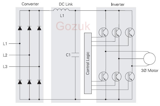
Variable frequency drive Rectifier
 To understand variable frequency drive (VFD) better, it's necessary to explain some of the main parts of the variable frequency ...
To understand variable frequency drive (VFD) better, it's necessary to explain some of the main parts of the variable frequency ...VFD controlled Induction motor ...
 This paper presents a procedure to measure the efficiency on an induction motor fed by a VFD by the all operation range to speed ...
This paper presents a procedure to measure the efficiency on an induction motor fed by a VFD by the all operation range to speed ...What is VFD, How it works? - VFD ...
 VFD is shorted for Variable Frequency Drive (also known as AC Drives and Inverters) -- that's used to make an AC motor working in ...
VFD is shorted for Variable Frequency Drive (also known as AC Drives and Inverters) -- that's used to make an AC motor working in ...VFD: Insulated Gate Bipolar Transistor ...
 IGBT (insulated gate bipolar transistor) provides a high switching speed necessary for PWM VFD operation. IGBTs are capable of ...
IGBT (insulated gate bipolar transistor) provides a high switching speed necessary for PWM VFD operation. IGBTs are capable of ...VFD: Pulse Width Modulation (PWM)
 Pulse Width Modulation (PWM) VFDs provide a more sinusoidal current output to control frequency and voltage supplied to an AC ...
Pulse Width Modulation (PWM) VFDs provide a more sinusoidal current output to control frequency and voltage supplied to an AC ...
VFD manufacturers