Connecting variable frequency drive to motor
Gozuk VFD specialists recommend connecting the motor to the variable frequency drive using shielded cables.
Connect in delta connection or star connection according to the motor data.
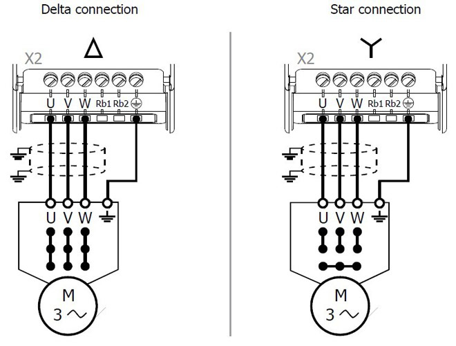
Maximum tightening torque: 0.5 Nm
Length of VFD cables, without filter
Permissible length of VFD cable without output filter
The specified lengths of the variable frequency drive cables must not be exceeded if no output filter is installed.
VFD cable length, with output filter dU/dt
Longer variable frequency drive cables can be used after taking appropriate measures, e.g. use of low-capacitance cables and output filters. The following table contains recommended values for the use of output filters.
VFD cable length with output filter
VFD cable length, with sinus filter
Variable frequency drive cables can be longer if sinus filters are used. By conversion in sinus-shaped currents, high frequency portions which might limit the VFD cable length are filtered out. Consider the voltage drop across the cable length and the resulting voltage drop at the sinus filter. The voltage drop results in an increase of the output current. The variable frequency drive must be suitable for the higher output current. This must be considered in the projecting phase.
In the case of variable frequency drive cable lengths exceeding 300 m, contact the VFD manufacturers service.
Group VFD
In the case of a group VFD (several motors at one variable frequency drive), the total length must be divided across the individual motors according to the value given in the table.
Use a thermal monitoring element on each motor (e.g. PTC resistor) in order to avoid damage. A group VFD with synchronous server motors is not possible.
Brake resistor
Gozuk recommends installing a brake resistor to the variable frequency drive if feedback of generator energy is expected. Overvoltage shutdowns can be avoided by this.
Warning!
 During operation, the surface of the brake resistor can reach high temperatures. The surface can keep high temperatures after operation for a certain time. Do not touch the brake resistor during operation or operational readiness of the variable frequency drive. Noncompliance may result in skin burn.
Install a safeguard for protection against contact or fix warning labels. Do not install the brake resistor in the proximity to flammable or heat-sensitive materials. Do not cover the brake resistor.
Caution!
Gozuk recommends using a temperature switch. The brake resistors available from Gozuk in resistor size 4 (92 Ohm, 696 W continuous power) and above are equipped with a temperature switch by standard. In resistor sizes 2 and 3 (300 Ohm, 213 W and 136 Ohm, 471 W) the temperature switch is available optional. The temperature switch disconnects the variable frequency drive from mains supply if the brake resistor is overloaded.
Using Brake resistors without temperature switches can result in critical states.
Minimize cable lengths
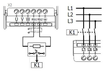
DC-connection requires a power estimation of the complete system. The brake resistor is operational dependent on the enable of the variable frequency drive. The contactor K1 must disconnect all plant components from the mains.
- Connect the cable shield to PE potential properly, i.e. with good conductivity, on both sides.
- The motor cables must be kept physically separate from the control and network cables.
Connect in delta connection or star connection according to the motor data.

Maximum tightening torque: 0.5 Nm
Length of VFD cables, without filter
Permissible length of VFD cable without output filter
|
Variable frequency drive |
unshielded cable |
shielded cable |
|
0.37 kW … 2.2 kW |
50 m |
25 m |
|
4.0 kW |
100 m |
50 m |
|
5.5 kW… 11.0 kW |
100 m |
50 m |
VFD cable length, with output filter dU/dt
Longer variable frequency drive cables can be used after taking appropriate measures, e.g. use of low-capacitance cables and output filters. The following table contains recommended values for the use of output filters.
VFD cable length with output filter
|
Variable frequency drive |
unshielded cable |
shielded cable |
|
0.37 kW … 2.2 kW |
150 m |
100 m |
|
4.0 kW |
300 m |
200 m |
|
5.5 kW… 11.0 kW |
300 m |
200 m |
VFD cable length, with sinus filter
Variable frequency drive cables can be longer if sinus filters are used. By conversion in sinus-shaped currents, high frequency portions which might limit the VFD cable length are filtered out. Consider the voltage drop across the cable length and the resulting voltage drop at the sinus filter. The voltage drop results in an increase of the output current. The variable frequency drive must be suitable for the higher output current. This must be considered in the projecting phase.
In the case of variable frequency drive cable lengths exceeding 300 m, contact the VFD manufacturers service.
Group VFD
In the case of a group VFD (several motors at one variable frequency drive), the total length must be divided across the individual motors according to the value given in the table.
Use a thermal monitoring element on each motor (e.g. PTC resistor) in order to avoid damage. A group VFD with synchronous server motors is not possible.
Brake resistor
Gozuk recommends installing a brake resistor to the variable frequency drive if feedback of generator energy is expected. Overvoltage shutdowns can be avoided by this.
Warning!
 During operation, the surface of the brake resistor can reach high temperatures. The surface can keep high temperatures after operation for a certain time. Do not touch the brake resistor during operation or operational readiness of the variable frequency drive. Noncompliance may result in skin burn.
Install a safeguard for protection against contact or fix warning labels. Do not install the brake resistor in the proximity to flammable or heat-sensitive materials. Do not cover the brake resistor.
Caution!
Gozuk recommends using a temperature switch. The brake resistors available from Gozuk in resistor size 4 (92 Ohm, 696 W continuous power) and above are equipped with a temperature switch by standard. In resistor sizes 2 and 3 (300 Ohm, 213 W and 136 Ohm, 471 W) the temperature switch is available optional. The temperature switch disconnects the variable frequency drive from mains supply if the brake resistor is overloaded.
Using Brake resistors without temperature switches can result in critical states.
Minimize cable lengths

DC-connection requires a power estimation of the complete system. The brake resistor is operational dependent on the enable of the variable frequency drive. The contactor K1 must disconnect all plant components from the mains.
Post a Comment:
You may also like:
Featured Articles
What is VFD, How it works? - VFD ...
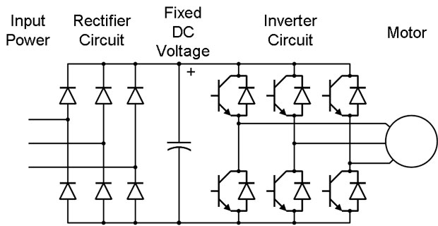 VFD is shorted for Variable Frequency Drive (also known as AC Drives and Inverters) -- that's used to make an AC motor working in ...
 VFD is shorted for Variable Frequency Drive (also known as AC Drives and Inverters) -- that's used to make an AC motor working in ...
VFD: Insulated Gate Bipolar Transistor ...
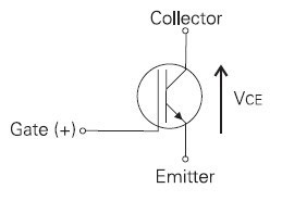 IGBT (insulated gate bipolar transistor) provides a high switching speed necessary for PWM VFD operation. IGBTs are capable of ...
 IGBT (insulated gate bipolar transistor) provides a high switching speed necessary for PWM VFD operation. IGBTs are capable of ...
Three phase inverters
 In the variable frequency drive rectifier paper, it explains how to go from three phase alternating current voltage to a direct ...
 In the variable frequency drive rectifier paper, it explains how to go from three phase alternating current voltage to a direct ...
Variable Frequency Drive Harmonics and ...
A discussion of the benefits of variable frequency drives often leads to a question regarding electrical harmonic distortion ...
Variable frequency drive Energy saving
 Energy can be saved in a VFD by reducing the losses in the electric motor or by reducing the energy consumption of the variable ...
 Energy can be saved in a VFD by reducing the losses in the electric motor or by reducing the energy consumption of the variable ...
VFD manufacturers
