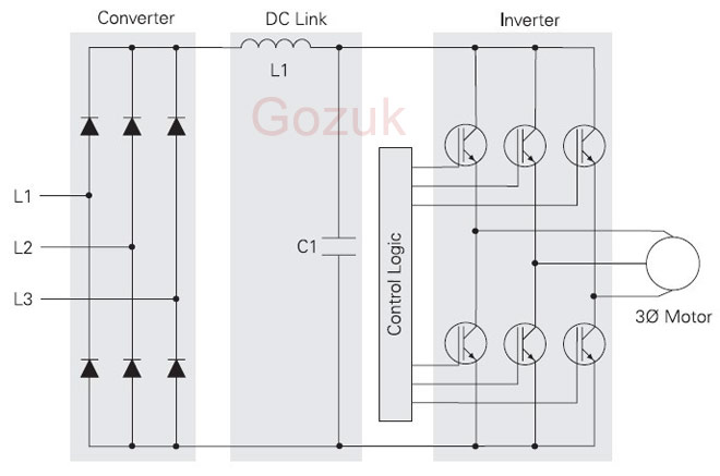
Effect of Variable Frequency Drive on motor insulation
The evolution of the power semiconductors have led to the creation of more efficient, but also faster, electronic switches. The high switching frequency of the IGBT transistors employed in modern variable frequency drives (VFD) bring about some undesirable effects, such as the increase of electromagnetic emission and the possibility of voltage peaks, as well as high dV/dt ratios (time derivative of the voltage, that is, rate of electrical potential rise), occurrence at the variable frequency drive fed motor terminals. Depending on the control characteristics (gate resistors, capacitors, command voltages, etc.) and the PWM adopted, when induction motors are fed by VFDs, those pulses combined with the impedances of both the cable and the motor may cause repetitive overvoltages on the motor terminals. This pulse train may degrade the motor insulation system and may hence reduce the motor lifetime.
The cable and the motor can be considered a resonant circuit, which is excited by the variable frequency drive rectangular pulses. When the values of R, L and C are such that the peak voltage exceeds the supply voltage (VDC ≈ 1.41 Vin), the circuit response to this excitation is a so called "overshoot". The overshoots affect especially the interturn insulation of random windings and depend on several factors: rise time of the voltage pulse, cable length and type, minimum time between successive pulses, switching frequency and multi-motor operation.
Rise Time
The PWM voltage takes some time to rise from its minimum to its maximum value. This period is often called "rise time". Due to the great rapidity of switching on the variable frequency drive stage, the growth of the voltage wavefront takes place too fast and, with the power electronics advance, these transition times tend to be more and more reduced.
Then the variable frequency drive fed motor is subjected to extremely high dV/ dt rates, so that the first turn of the first coil of a single phase is submitted to a high voltage level. Therefore VFD can considerably increase the voltage stress within a motor coil, though owing to the inductive and capacitive characteristics of the windings, the pulses are damped on the subsequent coils.

So the rise time (tr) has a direct influence on the insulation life, because the faster the pulse wavefront grows, the greater the dV/dt ratio over the first coil and the higher the levels of voltage between turns, causing the insulation system to wear more quickly away. Thus the motor insulation system should present superior dielectric characteristics in order to stand the elevated voltage gradients occurring on PWM environment.
Normative considerations about rise time
The definitions of rise time (tr) according to NEMA and to IEC Standards differ, as shown below, allowing for interpretation divergences and conflicts between manufacturers and users of motors and VFDs.
NEMA MG1 Part 30

tr: time needed for the voltage to rise from 10 to 90% of the DC link voltage (≈ 1.41Vrated)
NEMA definition of dV/dt
Supposing the motor voltage Vrated = 460 V
IEC 60034-25

tr: time needed for the voltage to rise from 10% to 90% of the peak voltage at motor terminals
IEC definition of dV/dt
Supposing the motor voltage Vrated = 460 V
Owing to the differences existing between the rise time definitions given by NEMA and IEC, misunderstandings often happen when calculating the voltage gradient (dV/dt).
According to NEMA criterion the DC link voltage (≈ 1.41 Vin) must be taken as 100% voltage reference for the determination of rise time and the calculation of dV/dt. According to IEC criterion, however, the peak voltage arriving at the motor terminals is what must be taken as 100% voltage reference. Due to the cable, the rise time to be considered in IEC criterion will be normally higher than the one considered in NEMA criterion (which is the value informed by the variable frequency drive manufacturer). Thus depending on the criteria considered throughout the calculations, pretty different values of dV/dt are likely to be attributed to the same situation.
The insulation criteria defined for Gozuk motors are based on NEMA, in order not to depend on the final customer installation. Furthermore the NEMA criterion seems appropriate for considering just the linear stretch of the curve to approximate the derivative (dV/dt ≡ △V/△t). The IEC criterion considers the peak voltage at the motor terminals, something extremely complicated to be predicted or estimated a priori. The rise time at the motor terminals is increased by the cable high frequency impedance. The dV/dt ratio at the motor terminals (milder than at the VFD terminals) can be also calculated, but it requires a reliable measurement of the voltage pulses at the motor leads and most of times this is not easily accomplished or not even feasible, demanding a technician familiar with such applications equipped with a good oscilloscope.
Cable length
Beside the rise time, the cable length is a predominant factor influencing the voltage peaks occurrence at the variable frequency drive fed motor terminals. The cable can be considered a transmission line with impedances distributed in sections of inductances / capacitances series / parallel connected. At each pulse, the variable frequency drive delivers energy to the cable, charging those reactive elements.

The signal arriving at the motor through the cable is partially reflected, causing overvoltage, because the motor high frequency impedance is greater than the cable impedance. Excessively long leads increase the overshoots at the motor terminals. According to the NEMA Application Guide for AC variable frequency drive systems, with the modern IGBT controls overshoots begin to occur with a cable length of a few feet and can reach 2 times the control DC bus voltage at a length less than 50 feet. In some cases, however, very long cables (in excess of 400 feet, for example) can result in a situation where the overshoot does not decay quickly enough. In this case the voltage peak at the motor terminals can ring up well beyond 2 times the variable frequency drive DC link voltage. This behavior is a function of the PWM pulse pattern, the rise time and the very cable type. Voltage measurements realized at the variable frequency drive terminals (0 feet cable) and at the motor (Vrated = 400 V) terminals with different cable lengths are presented next. The overshoots also depend on the type of cable used in the installation; therefore the waveforms shown below are illustrative only.
Corona effect
Depending on the quality/homogeneity of the impregnation the impregnating material may contain voids (cavities), in which the failure mechanism of the interturn insulation develops. The deterioration of the motor insulating system due to the voltage overshoots occurs by means of Partial Discharges (PD), a complex phenomenon resulting from Corona.
Between adjacent charged conductors there is relative voltage, which gives rise to an electric field. If the established electric field is high enough (but below the breakdown voltage of the insulating material), the dielectric strength of the air is disrupted, that is, if there is sufficient energy, oxygen (O2) is ionized in ozone (O3). The ozone is highly aggressive and attacks the organic components of the insulation system damaging it. For this to happen though the voltage on the conductors must exceed a threshold value, the so called "Corona Inception Voltage", that is the local breakdown strength in air (within the void). The CIV depends on the windings design, insulation type, temperature, superficial characteristics and moisture.

Partial discharge effect on the motor insulation system

Damaged insulation due to PD activity
Partial Discharge is thus a low energy discharge which, after long term activity, prematurely degrades the motor insulation. The erosion reduces the thickness of the insulating material, resulting in a progressive reduction of its dielectric properties, until its breakdown voltage capability falls below the level of the applied voltage peak, then the insulation breakdown occurs.
Minimum time between successive pulses (MTBP)
The voltage measurements presented above show that there is a succession of peaks in the voltage waveform delivered by the VFD and arriving at the motor terminals. This signal propagates trough the cable at a determined velocity. Depending on the winding characteristics and, with respect to the waveform, on the minimum time between successive pulses, the voltage appearing between turns may vary sensibly.
The average voltage applied at the motor terminals is controlled by the width of the pulses and by the time between them. The overshoots get worse with shorter times between pulses. This condition is most likely to occur at high peak or high output voltages and during transient conditions, such as acceleration or deceleration. If the time between pulses is less than three times the resonant period of the cable (typically 0.2 to 2 μs for industrial cable), then additional overshoot will occur. The only way to be sure that this condition does not exist is by measuring the pulses directly or by contacting the control manufacturer.
When the time between successive pulses is less than 6 μs, particularly when the first and the last turns of a single coil of a random winding are side by side, it may be assumed that the voltage between adjacent conductors is the peak to peak value between pulses. This fact results from the rapidity of the pulse propagation within a coil, because while the first turn stands a peak to peak voltage value, the voltage on the last turn is very low, probably zero.
In the case of the example shown above the MTBP was below 6 μs and there were actually motor failures due to short circuit between turns.

Switching frequency (fs)
Beside the effects caused by the rise time and the MTBP, there is also the frequency at which they are generated. Differently from eventual impulses caused by line handles, it is about a pulse train supported at a certain frequency. Owing to the fast developments on power electronics, presently this frequency reaches easily values such as 20 kHz. The higher the switching frequency, the faster the degradation of the motor insulation takes place. Studies bear out that there is no simple interrelation between the insulation life and the switching frequency, in spite of that experiences have shown interesting data:
Multiple motors
If more than one motor is connected to a control, there can be additional overshoot due to reflections from each motor. The situation is made worse when there is a long length of lead between the control and the common connection of motors. This length of lead acts to decouple the motor from the control. As a result, reflections which would normally be absorbed by the low impedance of the control can be carried to another motor and add to the overshoot at its terminals.

When connecting multiple motors to a single variable frequency drive, L must be as short as possible.
The cable and the motor can be considered a resonant circuit, which is excited by the variable frequency drive rectangular pulses. When the values of R, L and C are such that the peak voltage exceeds the supply voltage (VDC ≈ 1.41 Vin), the circuit response to this excitation is a so called "overshoot". The overshoots affect especially the interturn insulation of random windings and depend on several factors: rise time of the voltage pulse, cable length and type, minimum time between successive pulses, switching frequency and multi-motor operation.
Rise Time
The PWM voltage takes some time to rise from its minimum to its maximum value. This period is often called "rise time". Due to the great rapidity of switching on the variable frequency drive stage, the growth of the voltage wavefront takes place too fast and, with the power electronics advance, these transition times tend to be more and more reduced.
Then the variable frequency drive fed motor is subjected to extremely high dV/ dt rates, so that the first turn of the first coil of a single phase is submitted to a high voltage level. Therefore VFD can considerably increase the voltage stress within a motor coil, though owing to the inductive and capacitive characteristics of the windings, the pulses are damped on the subsequent coils.
So the rise time (tr) has a direct influence on the insulation life, because the faster the pulse wavefront grows, the greater the dV/dt ratio over the first coil and the higher the levels of voltage between turns, causing the insulation system to wear more quickly away. Thus the motor insulation system should present superior dielectric characteristics in order to stand the elevated voltage gradients occurring on PWM environment.
Normative considerations about rise time
The definitions of rise time (tr) according to NEMA and to IEC Standards differ, as shown below, allowing for interpretation divergences and conflicts between manufacturers and users of motors and VFDs.
NEMA MG1 Part 30
tr: time needed for the voltage to rise from 10 to 90% of the DC link voltage (≈ 1.41Vrated)
NEMA definition of dV/dt
Supposing the motor voltage Vrated = 460 V
Vlink DC ≈ 1,41 x 460 = 648,6 VAssuming that rise time = 0,1μs
△V = 0,8 x 648,6 = 518,9 V
△t = 0,1μs
DV/dt = △V/△t = 518,9 / 0,1 = 5189 [V/μs]
IEC 60034-25
tr: time needed for the voltage to rise from 10% to 90% of the peak voltage at motor terminals
IEC definition of dV/dt
Supposing the motor voltage Vrated = 460 V
△V = 0,8 x 1200 = 960 VAssuming tr = 0,25μs:
DV/dt = △V/△t = 518,9 / 0,25 = 3840 [V/μs]NOTE: Due to the cable, the rise time is higher at the motor terminals than at the variable frequency drive terminals. However, a very common mistake in the dV/dt calculation is to consider the rise time at the variable frequency drive terminals and the voltage peak at the motor terminals, resulting in an unlikely dV/dt value. For instance, considering tr = 0.1 μs (typical value found at the variable frequency drive) in the case above it would result dV/dt = 9600 V/μs!
Owing to the differences existing between the rise time definitions given by NEMA and IEC, misunderstandings often happen when calculating the voltage gradient (dV/dt).
According to NEMA criterion the DC link voltage (≈ 1.41 Vin) must be taken as 100% voltage reference for the determination of rise time and the calculation of dV/dt. According to IEC criterion, however, the peak voltage arriving at the motor terminals is what must be taken as 100% voltage reference. Due to the cable, the rise time to be considered in IEC criterion will be normally higher than the one considered in NEMA criterion (which is the value informed by the variable frequency drive manufacturer). Thus depending on the criteria considered throughout the calculations, pretty different values of dV/dt are likely to be attributed to the same situation.
The insulation criteria defined for Gozuk motors are based on NEMA, in order not to depend on the final customer installation. Furthermore the NEMA criterion seems appropriate for considering just the linear stretch of the curve to approximate the derivative (dV/dt ≡ △V/△t). The IEC criterion considers the peak voltage at the motor terminals, something extremely complicated to be predicted or estimated a priori. The rise time at the motor terminals is increased by the cable high frequency impedance. The dV/dt ratio at the motor terminals (milder than at the VFD terminals) can be also calculated, but it requires a reliable measurement of the voltage pulses at the motor leads and most of times this is not easily accomplished or not even feasible, demanding a technician familiar with such applications equipped with a good oscilloscope.
Cable length
Beside the rise time, the cable length is a predominant factor influencing the voltage peaks occurrence at the variable frequency drive fed motor terminals. The cable can be considered a transmission line with impedances distributed in sections of inductances / capacitances series / parallel connected. At each pulse, the variable frequency drive delivers energy to the cable, charging those reactive elements.
The signal arriving at the motor through the cable is partially reflected, causing overvoltage, because the motor high frequency impedance is greater than the cable impedance. Excessively long leads increase the overshoots at the motor terminals. According to the NEMA Application Guide for AC variable frequency drive systems, with the modern IGBT controls overshoots begin to occur with a cable length of a few feet and can reach 2 times the control DC bus voltage at a length less than 50 feet. In some cases, however, very long cables (in excess of 400 feet, for example) can result in a situation where the overshoot does not decay quickly enough. In this case the voltage peak at the motor terminals can ring up well beyond 2 times the variable frequency drive DC link voltage. This behavior is a function of the PWM pulse pattern, the rise time and the very cable type. Voltage measurements realized at the variable frequency drive terminals (0 feet cable) and at the motor (Vrated = 400 V) terminals with different cable lengths are presented next. The overshoots also depend on the type of cable used in the installation; therefore the waveforms shown below are illustrative only.
|
VFD terminals |
65.5 ft cable |
 |
 |
|
Vpeak = 560 V |
Vpeak = 630V |
|
98.5 ft cable |
328 ft cable |
 |
 |
|
Vpeak = 750V |
Vpeak = 990V |
Corona effect
Depending on the quality/homogeneity of the impregnation the impregnating material may contain voids (cavities), in which the failure mechanism of the interturn insulation develops. The deterioration of the motor insulating system due to the voltage overshoots occurs by means of Partial Discharges (PD), a complex phenomenon resulting from Corona.
Between adjacent charged conductors there is relative voltage, which gives rise to an electric field. If the established electric field is high enough (but below the breakdown voltage of the insulating material), the dielectric strength of the air is disrupted, that is, if there is sufficient energy, oxygen (O2) is ionized in ozone (O3). The ozone is highly aggressive and attacks the organic components of the insulation system damaging it. For this to happen though the voltage on the conductors must exceed a threshold value, the so called "Corona Inception Voltage", that is the local breakdown strength in air (within the void). The CIV depends on the windings design, insulation type, temperature, superficial characteristics and moisture.
Partial discharge effect on the motor insulation system
Damaged insulation due to PD activity
Partial Discharge is thus a low energy discharge which, after long term activity, prematurely degrades the motor insulation. The erosion reduces the thickness of the insulating material, resulting in a progressive reduction of its dielectric properties, until its breakdown voltage capability falls below the level of the applied voltage peak, then the insulation breakdown occurs.
Minimum time between successive pulses (MTBP)
The voltage measurements presented above show that there is a succession of peaks in the voltage waveform delivered by the VFD and arriving at the motor terminals. This signal propagates trough the cable at a determined velocity. Depending on the winding characteristics and, with respect to the waveform, on the minimum time between successive pulses, the voltage appearing between turns may vary sensibly.
The average voltage applied at the motor terminals is controlled by the width of the pulses and by the time between them. The overshoots get worse with shorter times between pulses. This condition is most likely to occur at high peak or high output voltages and during transient conditions, such as acceleration or deceleration. If the time between pulses is less than three times the resonant period of the cable (typically 0.2 to 2 μs for industrial cable), then additional overshoot will occur. The only way to be sure that this condition does not exist is by measuring the pulses directly or by contacting the control manufacturer.
When the time between successive pulses is less than 6 μs, particularly when the first and the last turns of a single coil of a random winding are side by side, it may be assumed that the voltage between adjacent conductors is the peak to peak value between pulses. This fact results from the rapidity of the pulse propagation within a coil, because while the first turn stands a peak to peak voltage value, the voltage on the last turn is very low, probably zero.
In the case of the example shown above the MTBP was below 6 μs and there were actually motor failures due to short circuit between turns.
Switching frequency (fs)
Beside the effects caused by the rise time and the MTBP, there is also the frequency at which they are generated. Differently from eventual impulses caused by line handles, it is about a pulse train supported at a certain frequency. Owing to the fast developments on power electronics, presently this frequency reaches easily values such as 20 kHz. The higher the switching frequency, the faster the degradation of the motor insulation takes place. Studies bear out that there is no simple interrelation between the insulation life and the switching frequency, in spite of that experiences have shown interesting data:
- If fs ≤ 5 kHz the probability of insulation failure occurrence is directly proportional to the switching frequency
- If fs > 5 kHz the probability of insulation failure occurrence is quadratically proportional to the switching frequency.
Multiple motors
If more than one motor is connected to a control, there can be additional overshoot due to reflections from each motor. The situation is made worse when there is a long length of lead between the control and the common connection of motors. This length of lead acts to decouple the motor from the control. As a result, reflections which would normally be absorbed by the low impedance of the control can be carried to another motor and add to the overshoot at its terminals.
When connecting multiple motors to a single variable frequency drive, L must be as short as possible.
Post a Comment:
You may also like:
Featured Articles
Variable frequency drive Rectifier
 To understand variable frequency drive (VFD) better, it's necessary to explain some of the main parts of the variable frequency ...
To understand variable frequency drive (VFD) better, it's necessary to explain some of the main parts of the variable frequency ...VFD controlled Induction motor ...
 This paper presents a procedure to measure the efficiency on an induction motor fed by a VFD by the all operation range to speed ...
This paper presents a procedure to measure the efficiency on an induction motor fed by a VFD by the all operation range to speed ...What is VFD, How it works? - VFD ...
 VFD is shorted for Variable Frequency Drive (also known as AC Drives and Inverters) -- that's used to make an AC motor working in ...
VFD is shorted for Variable Frequency Drive (also known as AC Drives and Inverters) -- that's used to make an AC motor working in ...VFD: Pulse Width Modulation (PWM)
 Pulse Width Modulation (PWM) VFDs provide a more sinusoidal current output to control frequency and voltage supplied to an AC ...
Pulse Width Modulation (PWM) VFDs provide a more sinusoidal current output to control frequency and voltage supplied to an AC ...Variable frequency drive Advantages & ...
VFDs are good for variable speed, in a water pump this is used to maintain a steady pressure, they will smooth out variances in ...

VFD manufacturers