Variable frequency drive Cold Plate
The "Cold Plate" variant enables installation of the variable frequency drive on suitable surfaces which have sufficient thermal conductivity to dissipate the heat developing during the operation of the variable frequency drive. Cooling is realized by means of a sufficient cooling area of the mounting plate or via an additional cooler.
Range of application
The "Cold Plate" variant enables the use of the variable frequency drive in the following applications:
The heat in the variable frequency drive due to the energy dissipation of the electronic components (rectifier and IGBT) must be dissipated to a heat sink via the cold plate of the variable frequency drive.
The capacity to dissipate this heat mainly depends on
The variable frequency drive must be mounted with the cold plate on an external heat sink with the lowest thermal resistance possible.
Thermal resistance
The thermal resistance Rth is calculated from the difference between the maximum heat sink temperature and the ambient temperature, referred to the energy dissipation of the variable frequency drive. The ambient temperature to be considered refers to the immediate environment of the variable frequency drive.
Rth = (Th max - Ta) / Pd
The thermal resistance values and the technical data apply in the following conditions:
Separation of energy dissipation:
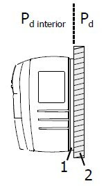
Pd interior: Energy dissipation, interior
Pd: Energy dissipation, heat sink
1: Cold Plate of variable frequency drive
2: Mounting plate as external heat sink
Additional fan or liquid cooling
The size of the heat sink can be reduced if fans are installed or a liquid cooling system is used in addition to the "Cold Plate" assembly. The size of the external heat sink can be reduced proportionally to the increase in the flow rate of the
cooling medium.
In the following a fan cooling system is described as an example. For calculating the maximum permissible heat resistance Rth enforced for cooling by means of a fan, a proportionality factor is introduced. This factor describes the increase of the VFD maximum permissible thermal resistance at increasing flow rate of the cooling air.
The maximum permissible thermal resistance Rth enforced for enforced air cooling can be calculated as follows:
α: Proportionality factor.
Application notes
Temperature monitoring
The heat sink temperature and the interior temperature can be monitored:
Error-switch-off is effected at:
Assembly
Warning!
 To avoid serious physical injury or considerable damage to property, only qualified staff may work on the variable frequency drives.
During operation, the heat sink can reach a temperature of up to 75 °C. Do not touch the heat sink during operation.
The heat sink may be hot even some time after the variable frequency drive was switched off.
Comply with the following requirements:
Deburr the threaded holes.
Clean the contact surfaces of the external heat sink and cold plate.
Apply a thin and uniform film of heat conducting paste on the cold plate.
Note:
The heat conducting paste compensates the roughness of the contact surfaces and thus the heat transmission resistance between the cold plate and the heat sink. In this way, the cooling efficiency is increased.
The maximum tightening torque of the fixing bolts in a typical construction is 3.4 Nm.
Range of application
The "Cold Plate" variant enables the use of the variable frequency drive in the following applications:
- Installation in a housing, where a high type of protection is required but the volume of the housing limits thermal compensation.
- Use in highly polluted cooling air affecting the function and service life of the VFD fan.
- Use of several variable frequency drives in limited space conditions, e.g. installation of variable frequency drives on a liquid-cooled plate (sum cooler).
- Direct assembly on (or in) a machine case, with parts of the machine constructions taking over the cooling function.
The heat in the variable frequency drive due to the energy dissipation of the electronic components (rectifier and IGBT) must be dissipated to a heat sink via the cold plate of the variable frequency drive.
The capacity to dissipate this heat mainly depends on
- the size of the heat sink surface,
- the ambient temperature and
- the heat transmission resistance.
The variable frequency drive must be mounted with the cold plate on an external heat sink with the lowest thermal resistance possible.
Thermal resistance
The thermal resistance Rth is calculated from the difference between the maximum heat sink temperature and the ambient temperature, referred to the energy dissipation of the variable frequency drive. The ambient temperature to be considered refers to the immediate environment of the variable frequency drive.
Rth = (Th max - Ta) / Pd
|
Max. permissible heat sink temperature of the variable frequency drive |
Th max = 75 °C |
|
Ambient temperature of the heat sink |
Ta = 35 °C |
|
Difference between the maximum heat sink temperature and the ambient temperature (Th max - Ta) |
△T = 40 K |
|
Energy to be dissipated by the heat sink |
Pd: device-specific |
The thermal resistance values and the technical data apply in the following conditions:
- No airflow.
- Clearance of approx. 300 mm above and below as well as 100 mm on both the left and right side of the variable frequency drive.
Separation of energy dissipation:

Pd interior: Energy dissipation, interior
Pd: Energy dissipation, heat sink
1: Cold Plate of variable frequency drive
2: Mounting plate as external heat sink
Additional fan or liquid cooling
The size of the heat sink can be reduced if fans are installed or a liquid cooling system is used in addition to the "Cold Plate" assembly. The size of the external heat sink can be reduced proportionally to the increase in the flow rate of the
cooling medium.
In the following a fan cooling system is described as an example. For calculating the maximum permissible heat resistance Rth enforced for cooling by means of a fan, a proportionality factor is introduced. This factor describes the increase of the VFD maximum permissible thermal resistance at increasing flow rate of the cooling air.
The maximum permissible thermal resistance Rth enforced for enforced air cooling can be calculated as follows:
Rth enforced = Rth / αRth: Maximum permissible thermal resistance with free circulation of air.
α: Proportionality factor.
Application notes
- Comply with the operation diagrams for VFD power reductions (derating).
-
Comply with the thermal limiting values of the variable frequency drive.
- Additional power losses Pd interior are dissipated as heat into the interior of a control cabinet. These losses may amount to 30% of the total energy dissipation and must be considered in the calculation of the volume of the control cabinet.
-
If several variable frequency drives or other heat-producing devices are mounted on a common heat sink (sum cooler), the losses of all devices must be added up.
- The contact surface of the external heat sink must have a sufficient thermal conductivity.
Temperature monitoring
The heat sink temperature and the interior temperature can be monitored:
- The temperatures can be displayed in the VFD actual value menu.
- When the maximum permitted temperatures are reached error-switch-off is effected and an error message is triggered.
- Before the VFD maximum permitted temperatures are reached a warning message is triggered. An error-switch-off can be avoided. The temperature values for the warnings can be set via VFD parameter.
Error-switch-off is effected at:
- Maximum heat sink temperature
- Maximum interior temperature
- the maximum heat sink temperature is reached (minus 5 °C)
- the maximum interior temperature is reached (minus 5 °C)
Assembly
Warning!
 To avoid serious physical injury or considerable damage to property, only qualified staff may work on the variable frequency drives.
During operation, the heat sink can reach a temperature of up to 75 °C. Do not touch the heat sink during operation.
The heat sink may be hot even some time after the variable frequency drive was switched off.
Comply with the following requirements:
- The installation surface of the external heat sink must at least be as large as the cold plate surface.
- The contact surfaces of the external heat sink and cold plate must be plane.
- The contact surfaces must be clean and degreased.
Deburr the threaded holes.
Clean the contact surfaces of the external heat sink and cold plate.
Apply a thin and uniform film of heat conducting paste on the cold plate.
Note:
The heat conducting paste compensates the roughness of the contact surfaces and thus the heat transmission resistance between the cold plate and the heat sink. In this way, the cooling efficiency is increased.
- Mount the variable frequency drive vertically on the heat sink using six M6 bolts. The bolts must have a minimum length of 30 mm. Tighten all bolts uniformly.
The maximum tightening torque of the fixing bolts in a typical construction is 3.4 Nm.
Post a Comment:
You may also like:
Featured Articles
Variable frequency drive Rectifier
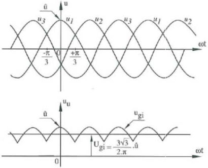 To understand variable frequency drive (VFD) better, it's necessary to explain some of the main parts of the variable frequency ...
 To understand variable frequency drive (VFD) better, it's necessary to explain some of the main parts of the variable frequency ...
VFD controlled Induction motor ...
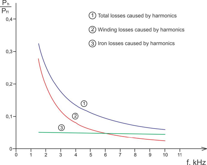 This paper presents a procedure to measure the efficiency on an induction motor fed by a VFD by the all operation range to speed ...
 This paper presents a procedure to measure the efficiency on an induction motor fed by a VFD by the all operation range to speed ...
VFD: Pulse Width Modulation (PWM)
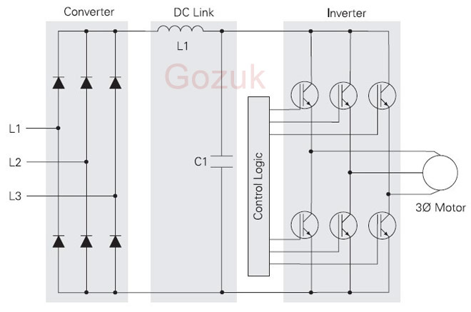 Pulse Width Modulation (PWM) VFDs provide a more sinusoidal current output to control frequency and voltage supplied to an AC ...
 Pulse Width Modulation (PWM) VFDs provide a more sinusoidal current output to control frequency and voltage supplied to an AC ...
Variable frequency drive Advantages & ...
VFDs are good for variable speed, in a water pump this is used to maintain a steady pressure, they will smooth out variances in ...
Variable frequency drive Energy saving
 Energy can be saved in a VFD by reducing the losses in the electric motor or by reducing the energy consumption of the variable ...
 Energy can be saved in a VFD by reducing the losses in the electric motor or by reducing the energy consumption of the variable ...
VFD manufacturers
