Flux Vector Variable Frequency Drive
A flux vector VFD uses feedback from what is happening at the motor to make changes in the output of the variable frequency drive.
However, it still relies on the basic volts per hertz core for controlling the motor. These combined techniques control not only the magnitude of motor flux but also its orientation, thus the flux vector name. The flux vector method provides more precise motor speed & torque control.
Flux vector control improves on the basic V/Hz control technique by providing both a magnitude & angle between the voltage & current. Volts per hertz variable frequency drives control only the magnitude. Vector VFDs come in two types, open loop & closed loop , based on the way they get their feedback information. Open loop is actually a misnomer because it’s actually a closed loop sys tem, but the feedback loop comes from within the variable frequency drive itself instead of an external encoder. For this reason there is a trend to refer to open-loop VFDs as sensor less vector VFDs. Sensorless vector control removes a major source of complexity & simplifies the variable frequency drive installation.
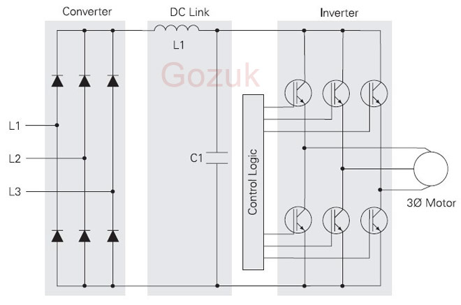
The block diagram of a sensorless flux vector control VFD is shown as:

Its operation can be summarized as follows:
A true closed-loop vector VFD can also make an AC motor develop continuous full torque at zero speed, something that previously only DC drives were capable of. That makes them suitable for crane & hoist in mining applications where the motor must produce full torque before the brake is released or else the load begins dropping & can't be stopped.
However, it still relies on the basic volts per hertz core for controlling the motor. These combined techniques control not only the magnitude of motor flux but also its orientation, thus the flux vector name. The flux vector method provides more precise motor speed & torque control.
Flux vector control improves on the basic V/Hz control technique by providing both a magnitude & angle between the voltage & current. Volts per hertz variable frequency drives control only the magnitude. Vector VFDs come in two types, open loop & closed loop , based on the way they get their feedback information. Open loop is actually a misnomer because it’s actually a closed loop sys tem, but the feedback loop comes from within the variable frequency drive itself instead of an external encoder. For this reason there is a trend to refer to open-loop VFDs as sensor less vector VFDs. Sensorless vector control removes a major source of complexity & simplifies the variable frequency drive installation.
The block diagram of a sensorless flux vector control VFD is shown as:
Its operation can be summarized as follows:
- Slip is the difference between the rotor speed & the synchronous speed of the magnetic field & is required to produce motor torque. The slip estimator block keeps actual motor rotor speed close to the desired set speed.
- The torque current estimator block determines the percent of current that is in phase with the voltage, providing an approximate torque current. This is used to estimate the amount of slip, providing better speed control under load.
- V angle controls the amount of total motor current that goes into motor flux enabled by the torque cur rent estimator. By controlling this angle, low-speed operation & torque control are improved over those of the standard V/Hz VFD.
- The flux vector control retains the V/Hz core & adds additional blocks around the core to improve the performance of the variable frequency drive.
- The current resolver attempts to identify the flux & torque producing currents in the motor & makes these values available to other blocks in the VFD.
- The current limit block monitors motor current & alters the frequency command when the motor current exceeds a predetermined value.
A true closed-loop vector VFD can also make an AC motor develop continuous full torque at zero speed, something that previously only DC drives were capable of. That makes them suitable for crane & hoist in mining applications where the motor must produce full torque before the brake is released or else the load begins dropping & can't be stopped.
Post a Comment:
You may also like:
Featured Articles
Variable frequency drive Rectifier
 To understand variable frequency drive (VFD) better, it's necessary to explain some of the main parts of the variable frequency ...
To understand variable frequency drive (VFD) better, it's necessary to explain some of the main parts of the variable frequency ...VFD controlled Induction motor ...
 This paper presents a procedure to measure the efficiency on an induction motor fed by a VFD by the all operation range to speed ...
This paper presents a procedure to measure the efficiency on an induction motor fed by a VFD by the all operation range to speed ...VFD: Pulse Width Modulation (PWM)
 Pulse Width Modulation (PWM) VFDs provide a more sinusoidal current output to control frequency and voltage supplied to an AC ...
Pulse Width Modulation (PWM) VFDs provide a more sinusoidal current output to control frequency and voltage supplied to an AC ...Variable frequency drive Advantages & ...
VFDs are good for variable speed, in a water pump this is used to maintain a steady pressure, they will smooth out variances in ...
Variable frequency drive Energy saving
 Energy can be saved in a VFD by reducing the losses in the electric motor or by reducing the energy consumption of the variable ...
Energy can be saved in a VFD by reducing the losses in the electric motor or by reducing the energy consumption of the variable ...
VFD manufacturers
can you help me?
I need manual of flux vector v5500 for control technique.
Do you have it?
best regard.