Vector VFD
Some VFD manufacturers provide additional circuits inside the VFD to allow the input of closed-loop feedback signals from encoders or resolvers. These circuits will decode the signals from the sensors and scale them to the level required. This feature makes the VFD operate more like a package system. This also makes it easier for design engineers to put a complete system together where all of the components match, Gozuk named this VFD with closed-loop capability a vector VFD. Its scalar VFD can be operated as either an open-loop or closed-loop VFD. Other manufactures provide similar packages. It is important to remember that the vector and scalar VFDs are more expensive and more complex than a simple VFD. A fractional horsepower VFDs cost less than $600 today.
In many ways, vector VFDs offer users the best features of both AC VFDs and DC VFDs in a single, problem-solving package. New electronics technology has dramatically reduced the complexity and cost of vector VFDs to make them practical for new uses.
Vector VFDs Provide Independent Control
What is a vector VFD and where does it get that mysterious name? You may recall from math classes that a "vector" quantity has both magnitude and direction. A vector VFD borrows that name, since it uses a more sophisticated electronic regulator to control both the magnitude and direction (or strength and speed) of the magnetic flux in an AC motor through independent control loops.
Conventional "variable-voltage, variable-frequency" (VVVF) AC VFDs lock together the excitation control of the magnitude and direction of magnetic flux in the motor.
The control strategy of VVVF VFDs is fine for steady-state conditions, or for loads encountered in applications such as variable frequency drive for water pumps and fans that allow lots of time for a speed change. But in many real-world applications, loads, speed, or position are likely to change abruptly. Vector VFDs are much better suited to handle these conditions since they provide direct torque control, as well as a dynamic response capability that is ten times that of WVF VFDs.
The block diagrams in Figures 1, 2, and 3 provide more details about the similarities and differences between vector VFDs and conventional VVVF VFDs.
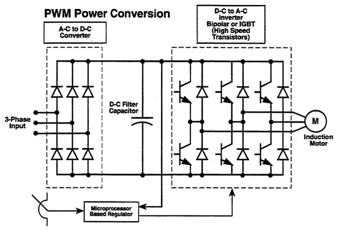
Figure 1 - Pulse Width Modulation (PWM) Technology
Note first the power conversion section shown in Figure 1. That portion of the VFD is common to virtually all pulse-width-modulated (PWM) VFDs, whether they use a VVVF or vector regulator. Three-phase AC power flows through the six input diodes which rectify it into DC power of a fixed voltage. The DC power is smoothed by the filter capacitor. A set of six transistors with diodes in the switching section are controlled to tum the DC power back into AC power of variable voltage and frequency. That "synthesized AC" power is fed to the motor.

Figure 2 - Voltz/Hertz Block Diagram
Figure 2 shows a simplified block diagram of the regulator of a conventional VVVF VFD. The speed reference command from the user is fed to a ramp block to convert step-function speed changes to slower-changing ramps that limit current flow and save machine wear and tear. The signal then moves to a section that sets both the rate of change and strength of the magnetic field in the motor. It is important to recognize that the single-speed control input command controls both of these variables in a VVVF VFD.
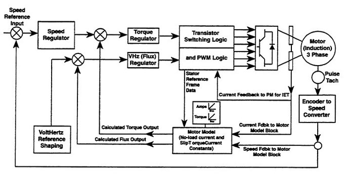
Figure 3 - Vector Block Diagram
A vector VFD regulator block diagram is shown in Figure 3. Two separate control loops have been added, making it more complex. The control loops allow independent control of the speed and strength of the motor's magnetic field. They also allow the regulator to measure the actual speed of the motor and to estimate closely the amount of torque being produced.
Although there are lots of advantages of vector VFD, you should also know the disadvantages of vector VFD.
In many ways, vector VFDs offer users the best features of both AC VFDs and DC VFDs in a single, problem-solving package. New electronics technology has dramatically reduced the complexity and cost of vector VFDs to make them practical for new uses.
Vector VFDs Provide Independent Control
What is a vector VFD and where does it get that mysterious name? You may recall from math classes that a "vector" quantity has both magnitude and direction. A vector VFD borrows that name, since it uses a more sophisticated electronic regulator to control both the magnitude and direction (or strength and speed) of the magnetic flux in an AC motor through independent control loops.
Conventional "variable-voltage, variable-frequency" (VVVF) AC VFDs lock together the excitation control of the magnitude and direction of magnetic flux in the motor.
The control strategy of VVVF VFDs is fine for steady-state conditions, or for loads encountered in applications such as variable frequency drive for water pumps and fans that allow lots of time for a speed change. But in many real-world applications, loads, speed, or position are likely to change abruptly. Vector VFDs are much better suited to handle these conditions since they provide direct torque control, as well as a dynamic response capability that is ten times that of WVF VFDs.
The block diagrams in Figures 1, 2, and 3 provide more details about the similarities and differences between vector VFDs and conventional VVVF VFDs.

Figure 1 - Pulse Width Modulation (PWM) Technology
Note first the power conversion section shown in Figure 1. That portion of the VFD is common to virtually all pulse-width-modulated (PWM) VFDs, whether they use a VVVF or vector regulator. Three-phase AC power flows through the six input diodes which rectify it into DC power of a fixed voltage. The DC power is smoothed by the filter capacitor. A set of six transistors with diodes in the switching section are controlled to tum the DC power back into AC power of variable voltage and frequency. That "synthesized AC" power is fed to the motor.

Figure 2 - Voltz/Hertz Block Diagram
Figure 2 shows a simplified block diagram of the regulator of a conventional VVVF VFD. The speed reference command from the user is fed to a ramp block to convert step-function speed changes to slower-changing ramps that limit current flow and save machine wear and tear. The signal then moves to a section that sets both the rate of change and strength of the magnetic field in the motor. It is important to recognize that the single-speed control input command controls both of these variables in a VVVF VFD.

Figure 3 - Vector Block Diagram
A vector VFD regulator block diagram is shown in Figure 3. Two separate control loops have been added, making it more complex. The control loops allow independent control of the speed and strength of the motor's magnetic field. They also allow the regulator to measure the actual speed of the motor and to estimate closely the amount of torque being produced.
Although there are lots of advantages of vector VFD, you should also know the disadvantages of vector VFD.
Post a Comment:
You may also like:
Featured Articles
What is VFD, How it works? - VFD ...
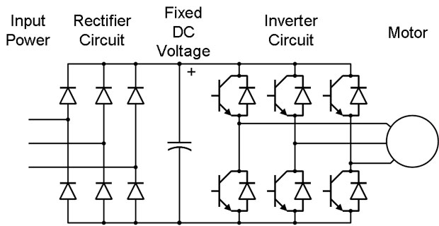 VFD is shorted for Variable Frequency Drive (also known as AC Drives and Inverters) -- that's used to make an AC motor working in ...
 VFD is shorted for Variable Frequency Drive (also known as AC Drives and Inverters) -- that's used to make an AC motor working in ...
VFD: Insulated Gate Bipolar Transistor ...
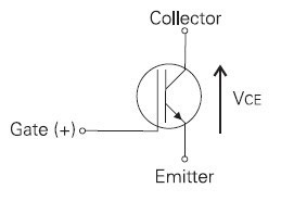 IGBT (insulated gate bipolar transistor) provides a high switching speed necessary for PWM VFD operation. IGBTs are capable of ...
 IGBT (insulated gate bipolar transistor) provides a high switching speed necessary for PWM VFD operation. IGBTs are capable of ...
Three phase inverters
 In the variable frequency drive rectifier paper, it explains how to go from three phase alternating current voltage to a direct ...
 In the variable frequency drive rectifier paper, it explains how to go from three phase alternating current voltage to a direct ...
Variable Frequency Drive Harmonics and ...
A discussion of the benefits of variable frequency drives often leads to a question regarding electrical harmonic distortion ...
Variable frequency drive Energy saving
 Energy can be saved in a VFD by reducing the losses in the electric motor or by reducing the energy consumption of the variable ...
 Energy can be saved in a VFD by reducing the losses in the electric motor or by reducing the energy consumption of the variable ...
VFD manufacturers
