Leakage current in opened switch
Well, even when the switch is open (i.e.) even when the fixed & moving contacts of the switching devices are apart, there is still an insulation between the fixed & moving contacts. Like any material in this earth, this insulating material also has an electrical resistance and this resistance is called Insulation Resistance. And, even when the switch is OFF, the incoming side would still be live with the system voltage. Wherever & whenever a voltage is there and a resistance is there, there is bound to be current flow, following Ohm's Law. True to this, there would definitely be a current flow between the open fixed & moving contacts of the switch, through this insulation resistance. This current is called the 'leakage current'.
And, the magnitude of this leakage current is decided by the incoming side voltage and the insulation resistance.
Interestingly, this is what is the difference between a switch and an isolator. In an isolator, under the worst conditions of 110% of input voltage and with minimum permissible insulation resistance, the leakage current shall be less than 2mA, which is the human perception level, under bare foot, wet floor conditions. That, is even under the worst possible conditions, a person working on the outgoing side of an open switch should not even perceive or feel the current through his body, thus avoiding deaths due to - not electric shock - but the psychological shock that the person would have when he/she starts perceiving the current flow. So, to qualify as an isolator, the leakage current through an open switch shall be less than the human perception level, even under the worst conditions.
In a switch, under the same conditions, a leakage current of more than 2mA is permissible.
Post a Comment:
You may also like:
Featured Articles
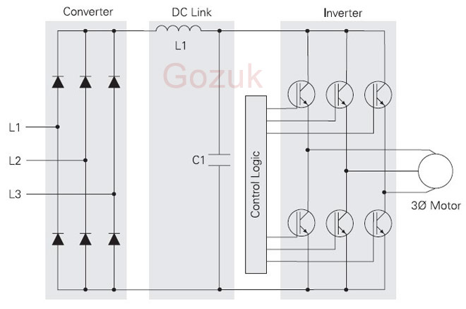
Variable frequency drive Rectifier
 To understand variable frequency drive (VFD) better, it's necessary to explain some of the main parts of the variable frequency ...
To understand variable frequency drive (VFD) better, it's necessary to explain some of the main parts of the variable frequency ...What is VFD, How it works? - VFD ...
 VFD is shorted for Variable Frequency Drive (also known as AC Drives and Inverters) -- that's used to make an AC motor working in ...
VFD is shorted for Variable Frequency Drive (also known as AC Drives and Inverters) -- that's used to make an AC motor working in ...VFD controlled Induction motor ...
 This paper presents a procedure to measure the efficiency on an induction motor fed by a VFD by the all operation range to speed ...
This paper presents a procedure to measure the efficiency on an induction motor fed by a VFD by the all operation range to speed ...VFD: Insulated Gate Bipolar Transistor ...
 IGBT (insulated gate bipolar transistor) provides a high switching speed necessary for PWM VFD operation. IGBTs are capable of ...
IGBT (insulated gate bipolar transistor) provides a high switching speed necessary for PWM VFD operation. IGBTs are capable of ...VFD: Pulse Width Modulation (PWM)
 Pulse Width Modulation (PWM) VFDs provide a more sinusoidal current output to control frequency and voltage supplied to an AC ...
Pulse Width Modulation (PWM) VFDs provide a more sinusoidal current output to control frequency and voltage supplied to an AC ...
VFD manufacturers