Understanding VFD circuit
(We already know how does VFD work, then it's better to understand what is the variable frequency drive circuit composed of.)
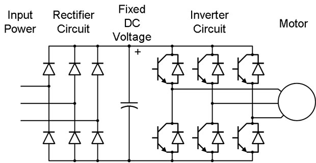
The solid-state circuitry of a VFD can be described as having three sections:
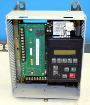
Fig. 1 Opened Variable Frequency Drive for troubleshooting
Following Fig. 2 diagram shows an electronic diagram of a Gozuk VFD. Each section of the VFD is shown with the actual components connected as you would find them when you opened the VFD to troubleshoot it (see Fig. 1). The rectifier section of this VFD utilizes a three-phase bridge rectifier, which is actually a module. This means it can be removed & replaced as a unit rather quickly if it fails. In a future article we will show a picture of this type of module & explain its internal operations. The output of the rectifier section is six half-waves. A set of metal-oxide varistors connected to the input of the rectifier section to protect against voltage surges.
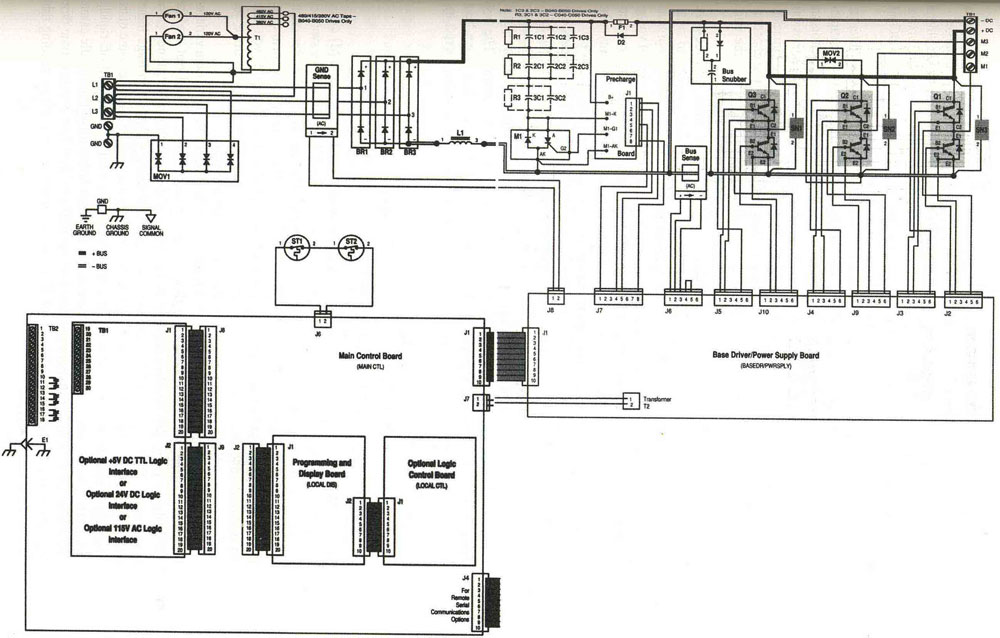
Fig. 2 (Click to see a full-resolution picture) Schematic of a VFD. The major components of the VFD include the rectifier, the filter, & the output transistors.
When the input voltage to the VFD is 480 volts ac, the output dc volts from the rectifier section will be approximately 670 volts dc. The pulsing DC voltage is applied to the DC bus on this system. The DC bus is identified by the +DC & the -DC wires that run through the length of the VFD circuit.
The filter section of the VFD uses capacitors & an inductor to filter the voltage & current. The capacitors have a pre-charge circuit that allows the capacitors to reach full charge slowly so that they are not damaged. The capacitors are connected in parallel with the DC bus, & the inductor is connected in series with the negative DC bus wire. A set of resistors is provided to discharge the capacitors anytime power is removed. You should always allow sufficient time for the capacitors to discharge before you try to work on the solid-state components in the VFD. The filter allows the pulsing DC voltage to be changed to pure DC.
The output section of the VFD converts the DC voltage back to three-phase voltage. This section uses pulse-width modulation (PWM) techniques to switches three pairs of transistors on & off up to 12 times during each half-wave to produce a three phase output. The amplitude of the signal determines the amount of voltage for the AC voltage, & the frequency of the signal will determine the frequency of the output of the VFD. In most cases the output frequency can be any value between 0-120 Hz. Some VFDs allow the upper frequency to reach 400 Hz.
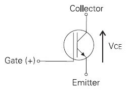
The output transistors are connected across the DC bus. One transistor is connected to the positive DC bus wire, & when it's switched on & off, it will provide the positive half-cycle for one phase of the AC signal. The second transistor is connected to the negative DC bus wire, & when it's switched on & off, it will provide the negative half-cycle for one phase of the AC signal. The base VFD board provides the PWM signals for all of the transistors. The VFD contains a microprocessor that accepts the command signal & determines the correct frequency & voltage for the output transistors.
The solid-state circuitry of a VFD can be described as having three sections:
- The first section of the VFD is called the rectifier section or converter. This section consists of a three-phase bridge rectifier.
- The second section of the VFD is called the DC intermediate section & it contains the filter components.
- The third block of the VFD is called the inverter section because this is where the DC voltage is turned back into three-phase AC voltage.

Fig. 1 Opened Variable Frequency Drive for troubleshooting
Following Fig. 2 diagram shows an electronic diagram of a Gozuk VFD. Each section of the VFD is shown with the actual components connected as you would find them when you opened the VFD to troubleshoot it (see Fig. 1). The rectifier section of this VFD utilizes a three-phase bridge rectifier, which is actually a module. This means it can be removed & replaced as a unit rather quickly if it fails. In a future article we will show a picture of this type of module & explain its internal operations. The output of the rectifier section is six half-waves. A set of metal-oxide varistors connected to the input of the rectifier section to protect against voltage surges.

Fig. 2 (Click to see a full-resolution picture) Schematic of a VFD. The major components of the VFD include the rectifier, the filter, & the output transistors.
When the input voltage to the VFD is 480 volts ac, the output dc volts from the rectifier section will be approximately 670 volts dc. The pulsing DC voltage is applied to the DC bus on this system. The DC bus is identified by the +DC & the -DC wires that run through the length of the VFD circuit.
The filter section of the VFD uses capacitors & an inductor to filter the voltage & current. The capacitors have a pre-charge circuit that allows the capacitors to reach full charge slowly so that they are not damaged. The capacitors are connected in parallel with the DC bus, & the inductor is connected in series with the negative DC bus wire. A set of resistors is provided to discharge the capacitors anytime power is removed. You should always allow sufficient time for the capacitors to discharge before you try to work on the solid-state components in the VFD. The filter allows the pulsing DC voltage to be changed to pure DC.
The output section of the VFD converts the DC voltage back to three-phase voltage. This section uses pulse-width modulation (PWM) techniques to switches three pairs of transistors on & off up to 12 times during each half-wave to produce a three phase output. The amplitude of the signal determines the amount of voltage for the AC voltage, & the frequency of the signal will determine the frequency of the output of the VFD. In most cases the output frequency can be any value between 0-120 Hz. Some VFDs allow the upper frequency to reach 400 Hz.
The output transistors are connected across the DC bus. One transistor is connected to the positive DC bus wire, & when it's switched on & off, it will provide the positive half-cycle for one phase of the AC signal. The second transistor is connected to the negative DC bus wire, & when it's switched on & off, it will provide the negative half-cycle for one phase of the AC signal. The base VFD board provides the PWM signals for all of the transistors. The VFD contains a microprocessor that accepts the command signal & determines the correct frequency & voltage for the output transistors.
When power failure and resumed occurred VFD's are trip shown frequently.
Post a Comment:
You may also like:
Featured Articles
What is VFD, How it works? - VFD ...
 VFD is shorted for Variable Frequency Drive (also known as AC Drives and Inverters) -- that's used to make an AC motor working in ...
 VFD is shorted for Variable Frequency Drive (also known as AC Drives and Inverters) -- that's used to make an AC motor working in ...
VFD: Insulated Gate Bipolar Transistor ...
 IGBT (insulated gate bipolar transistor) provides a high switching speed necessary for PWM VFD operation. IGBTs are capable of ...
 IGBT (insulated gate bipolar transistor) provides a high switching speed necessary for PWM VFD operation. IGBTs are capable of ...
Three phase inverters
 In the variable frequency drive rectifier paper, it explains how to go from three phase alternating current voltage to a direct ...
 In the variable frequency drive rectifier paper, it explains how to go from three phase alternating current voltage to a direct ...
Variable Frequency Drive Harmonics and ...
A discussion of the benefits of variable frequency drives often leads to a question regarding electrical harmonic distortion ...
Variable frequency drive Energy saving
 Energy can be saved in a VFD by reducing the losses in the electric motor or by reducing the energy consumption of the variable ...
 Energy can be saved in a VFD by reducing the losses in the electric motor or by reducing the energy consumption of the variable ...
VFD manufacturers
