You can use an external bypass to the pump including a manual (or controlled) valve. The opening of the valve will determine the flow rate at the outlet of the pump. The disadvantage is that as centrifugal pumps power consumption is proportional to flow, this solution is less efficient in terms of energy than closing a valve.Closing a valve may reduce a little bit energy consumption, bypassing the flow keeps it rather constant.
Positive displacement pumps are constant torque applications. To tell an old story, when I worked for a positive displacement pump company we sold packages with variable frequency drives. A salesman for a VFD manufacturer said he could save us money with their "pump" VFDs instead of the ones we were buying. I had to explain to him what he was selling and why it wouldn't work for our application. So be careful to know what type of pump you have when buying a VFD.
I know that you can use inverter duty motor with 10:1 ratio. while standard motor 2:1. I know VFD (variable frequency drive) operating range for positive displacement Pumps. Positive displacement Pumps never use Inverter duty motor even to getting a ratio 5:1 with 4 pole motor. Instead they prefer to use reduction drive, which decrease the overall efficiency of system and add extra cost.
Motor manufacturers classify their motors as inverter duty when they use a class F insulation. Will it give 4 time more life time than standard class A or B? Not really. They wind their motors per NEMA MG-1 classification.
The number of poles shouldn't have anything to do with it. You can vary a 6-pole motor just as easily as a 2-pole. You just get a different speed range out of the shaft. You can even go over speed. I've run regular induction motors at 75 hz before. With proper engineering attention, you can go a lot higher.
If you have to use a non-inverter duty motor with a Variable Frequency drive (VFD), it's wise to have some sort of harmonics filter, either a passive reactor or an active filter. It's the harmonics that can cause excess heating and in come cases very high transient voltages that can break down insulation. Mitigating harmonics after the variable frequency drive will reduce the chances of problems.
Q: I am currently using a V/F drive to control the forward/backward movement of a bogie and upward/downward movement of the door on a furnace. I am unable to achieve instantaneous stop of the doors. Can you suggest a remedy for this? Will using a braking resistor on the present variable frequency drive improve the situation? Do I need to use a vector VFD for this application?
A: There are too many unknowns. What size of the variable frequency drive? What is the inertia of the load? What is the speed? What is the acceleration/ deceleration time? Is it direct driven or through a gear box? If you need to control torque a vector variable frequency drive that gives access to the current or torque loop would be required. Do you have any feedback control? Do you have access to the DC bus so a brake chopper could be connected? If you use a brake chopper, the load inertia, time and stored energy are critical for sizing the resistor. This also assures the DC bus does not overvoltage and the brake IGBT current rating is not exceeded.
A: There are too many unknowns. What size of the variable frequency drive? What is the inertia of the load? What is the speed? What is the acceleration/ deceleration time? Is it direct driven or through a gear box? If you need to control torque a vector variable frequency drive that gives access to the current or torque loop would be required. Do you have any feedback control? Do you have access to the DC bus so a brake chopper could be connected? If you use a brake chopper, the load inertia, time and stored energy are critical for sizing the resistor. This also assures the DC bus does not overvoltage and the brake IGBT current rating is not exceeded.
As Variable Frequency Drives (VFD) gaining more acceptances among Fluid Power Engineers, ability to select and size correct electric motor and VFD is becoming more critical as applications are getting more demanding. I like to share my experiences here with you since I see common misapplications of motors and variable frequency drives. I hope you find them interesting and useful. I'll start with motor enclosure selection.
Wrong motor enclosure selection can results in complete design failure, especially in applications where a combination of VFD and fixed displacement pumps are used in variable flow with compensated pressure settings ("P" control mode). When using variable displacement pump with Fixed RPM motor, it is desirable to use TENV (Totally Enclosed None Ventilated) or TEFC (Totally Enclosed Fan Cooled) frame motors, since they have relatively larger rotor diameter with inherently high rotor inertia. Rotors with high Inertia in Fixed RPM applications acts as a flywheel stabilizing motor RPM during rapid torque changes.
Wrong motor enclosure selection can results in complete design failure, especially in applications where a combination of VFD and fixed displacement pumps are used in variable flow with compensated pressure settings ("P" control mode). When using variable displacement pump with Fixed RPM motor, it is desirable to use TENV (Totally Enclosed None Ventilated) or TEFC (Totally Enclosed Fan Cooled) frame motors, since they have relatively larger rotor diameter with inherently high rotor inertia. Rotors with high Inertia in Fixed RPM applications acts as a flywheel stabilizing motor RPM during rapid torque changes.
Typically this type of variable frequency drive (VFD) is used for small scale applications where demand will be very low. Typically 220V single phase VFDs will be used on motor with a power rating of 1HP to 5HP this is enough to pump water from a well to a small reservoir but for more powerful motors it is best to stick with 3 phase. Your problem is difficult to solve with alternatives because electricity supply is the most critical part. Look at your motor power rating and then decide if this is going to work for you.
You should also look at the inertial load on the motor. A large inertial load will cause a greater regeneration level when the motor is slowing down. One way to correct for this is to increase the slow down ramp time, this should fix it albeit temporarily. If it is inertial in nature and quicker ramping is required, set up dynamic braking using a resistor and controller as mentioned earlier. Many variable frequency drives have the controller built in, so check your model's specifications.
If the VFD has DC bus overvoltage while stopped, check your incoming supply voltage. A high voltage excursion would cause this. The main power transformer taps may need to be changed in that case. If the power company's voltages vary too greatly, request the power company to install automatic tap changers on their transformer. Otherwise the only solution would be to use a regulated DC power supply and feed DC directly to the VFD and abandon the AC front end on the variable frequency drive.
If the VFD has DC bus overvoltage while stopped, check your incoming supply voltage. A high voltage excursion would cause this. The main power transformer taps may need to be changed in that case. If the power company's voltages vary too greatly, request the power company to install automatic tap changers on their transformer. Otherwise the only solution would be to use a regulated DC power supply and feed DC directly to the VFD and abandon the AC front end on the variable frequency drive.
DC Bus becomes more means DC Bus Overvoltage, ie. VFD DC Bus voltage exceeded its trip point.
For 200 V Class Variable Frequency Drive - Trip Point is 410 VIn Basic, if this may happen due to Surge Voltage present in the VFD Input Power. For that you have to provide AC Reactor or DC Reactor. Voltage surge can results from Thyristor convertor and a Phase advancing Capacitor operating on the same vfd drive input power.
For 400 V Class Variable Frequency Drive - Trip Point is 820 V
What you are attempting to do is very difficult. It is OK to run multiple simple drive motors on a single variable frequency drive (VFD) because you add up the motor loads and then you must use a Eutectic (bi-metallic) Overload for each motor after the VFD. The larger VFD for multiple motors together can not clearly detect only one motor overloading so a separate motor protection is required for each motor after the VFD. They should be the bi-metallic type because a VFD usually has very good short circuit protection or phase loss protection, better than an electronic OL. An electronic OL is usually never used after a VFD because of the Pulse-Width-Modulation output made by the VFD. It is not a standard sine wave through the electronic OL and does not work well. A bi-metallic OL heats up in the same way the motor coils heat up so they will detect each motor OL or fault and better protect the motors individually.
If you look at all the things you need to do to save a little money on one larger 20 HP VFD versus 2 smaller 10 HP VFDs in parallel, and add in all the proper protections, you are probably spending more money and will have more problems trying to control multiple motors on one VFD.
If you look at all the things you need to do to save a little money on one larger 20 HP VFD versus 2 smaller 10 HP VFDs in parallel, and add in all the proper protections, you are probably spending more money and will have more problems trying to control multiple motors on one VFD.
Any thoughts on changing a press motor system over from a card with a pulsed feedback to a variable frequency drive? Pulsed feedback indicates speed. The guys have it Jimmied at the moment to fake out the card. I've been told both, that I'd need a motor change and not, so investigating. They have a top speed on the press right now, but maintenance wise, I think it would cost us less and be less stress on the motor if we employed a VFD.
Considering only bearings for instance you can experience end of life with flacking, grease contamination, electrical pitting, grease evaporation, grease oxidation, controlled by VFD, etc... most of those mechanisms can be estimated (see IEEE literature). Fatigue life time (flacking) for instance can be estimate with ISO 281 (2007) or even with online tools. But I can tell you that all those tools methods will never be able to include all the influential parameters. For instance our main bearing suppliers claim that those methods are just a toy for those who have no idea or for those who have no past experience.
Featured Articles
Non-Enclosure Variable Frequency Drive ...
 No enclosure (cover), reducing installation space and cost effective. Widely used in All-In-One control cabinet. Keep the same ...
No enclosure (cover), reducing installation space and cost effective. Widely used in All-In-One control cabinet. Keep the same ...Variable frequency drive application ...
 Variable Frequency Drive (VFD) can be used in lots of fields. Variable frequency drives are widely used to control the speed of ...
Variable Frequency Drive (VFD) can be used in lots of fields. Variable frequency drives are widely used to control the speed of ...Variable frequency drive in HVAC ...
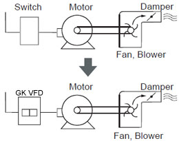
 Variable frequency drives (VFD) have been used for HVAC systems in buildings for more than 40 years. But only in recent years, ...
Variable frequency drives (VFD) have been used for HVAC systems in buildings for more than 40 years. But only in recent years, ...Variable Frequency Drive Harmonics and ...
A discussion of the benefits of variable frequency drives often leads to a question regarding electrical harmonic distortion ...
Three phase inverters
 In the variable frequency drive rectifier paper, it explains how to go from three phase alternating current voltage to a direct ...
In the variable frequency drive rectifier paper, it explains how to go from three phase alternating current voltage to a direct ...
VFD manufacturers