Variable Frequency Drive Digital Inputs
Digital inputs are used to interface the VFD with devices such as push buttons, selector switches, relay contacts & PLC digital output modules. Each digital input may have a preset function assigned to it, such as start/stop, forward/reverse, external fault, & preset speed selections. For example, if a motor has to operate at three different speeds, a relay or switch contact could be made to close & send signals to separate digital inputs points that would change the motor speed to the preset value.
Following diagram shows typical input digital connections for two-wire or three-wire control with stop, forward, reverse, & jogging functions. Because variable frequency drives are electronic devices, they can have only one phase rotation output at a time. Therefore, interlocking, as required on electromechanical devices, is not required for variable frequency drive for ward/reverse operations. Inputs can also be programmed for two- or three-wire control to accommodate either maintained or momentary start methods. Note that the control logic is determined & executed by the program within the VFD & not by the hard-wiring arrangement of the input control devices.
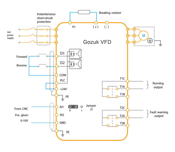
Digital/relay outputs. Digital/relay outputs are two position signals (on/off) sent by the variable frequency drive to devices such as pilot lights, alarms, auxiliary relays, solenoids, & PLC digital input modules. Digital outputs have a volt age potential (e.g., 24 V DC) coming from them. Relay outputs, which are known as "dry" contacts, switch some thing external, closing or opening another potential. Relay outputs are normally rated for both AC & DC voltages.
Analog inputs. Analog inputs are used to interface the VFD with an external 0-10 V DC or 4-20 mA signal, For example, a speed setpoint from an external speed control potentiometer.
Analog outputs. Analog outputs are modulating signals sent by the variable frequency drive to a device such as a meter that could display speed or current.
Following diagram shows typical input digital connections for two-wire or three-wire control with stop, forward, reverse, & jogging functions. Because variable frequency drives are electronic devices, they can have only one phase rotation output at a time. Therefore, interlocking, as required on electromechanical devices, is not required for variable frequency drive for ward/reverse operations. Inputs can also be programmed for two- or three-wire control to accommodate either maintained or momentary start methods. Note that the control logic is determined & executed by the program within the VFD & not by the hard-wiring arrangement of the input control devices.

Digital/relay outputs. Digital/relay outputs are two position signals (on/off) sent by the variable frequency drive to devices such as pilot lights, alarms, auxiliary relays, solenoids, & PLC digital input modules. Digital outputs have a volt age potential (e.g., 24 V DC) coming from them. Relay outputs, which are known as "dry" contacts, switch some thing external, closing or opening another potential. Relay outputs are normally rated for both AC & DC voltages.
Analog inputs. Analog inputs are used to interface the VFD with an external 0-10 V DC or 4-20 mA signal, For example, a speed setpoint from an external speed control potentiometer.
Analog outputs. Analog outputs are modulating signals sent by the variable frequency drive to a device such as a meter that could display speed or current.
to control pump speed by monitoring discharge pressure.what kind of input signal is required ? analog or digital and what range?
Post a Comment:
You may also like:
Featured Articles
Variable frequency drive Rectifier
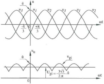 To understand variable frequency drive (VFD) better, it's necessary to explain some of the main parts of the variable frequency ...
 To understand variable frequency drive (VFD) better, it's necessary to explain some of the main parts of the variable frequency ...
What is VFD, How it works? - VFD ...
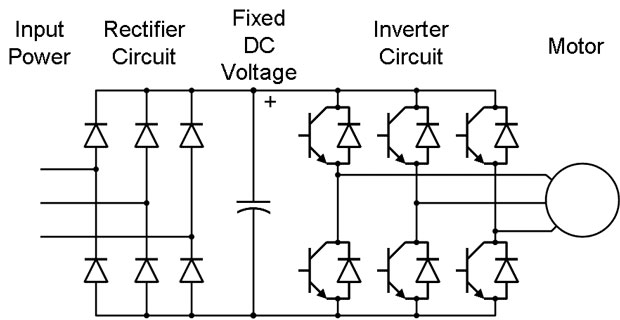 VFD is shorted for Variable Frequency Drive (also known as AC Drives and Inverters) -- that's used to make an AC motor working in ...
 VFD is shorted for Variable Frequency Drive (also known as AC Drives and Inverters) -- that's used to make an AC motor working in ...
VFD: Insulated Gate Bipolar Transistor ...
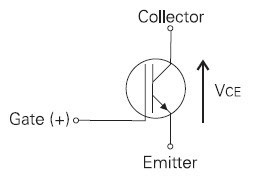 IGBT (insulated gate bipolar transistor) provides a high switching speed necessary for PWM VFD operation. IGBTs are capable of ...
 IGBT (insulated gate bipolar transistor) provides a high switching speed necessary for PWM VFD operation. IGBTs are capable of ...
VFD controlled Induction motor ...
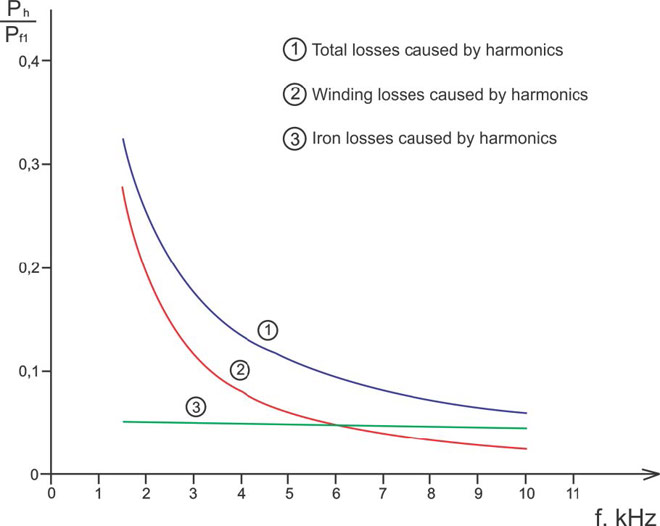 This paper presents a procedure to measure the efficiency on an induction motor fed by a VFD by the all operation range to speed ...
 This paper presents a procedure to measure the efficiency on an induction motor fed by a VFD by the all operation range to speed ...
Three phase inverters
 In the variable frequency drive rectifier paper, it explains how to go from three phase alternating current voltage to a direct ...
 In the variable frequency drive rectifier paper, it explains how to go from three phase alternating current voltage to a direct ...
VFD manufacturers
