VFD basics theory
Variable Frequency Drives (VFD, aka variable speed drive - VSD) have been available for use with a wide range of applications for over 20 years. These applications include single motor driven pumps, fans and compressors, as well as highly sophisticated multi-drive machines.
(this paper include VFD types, advantages of VFDs and disadvantages basics as a tutorial)
VFD's function to adjust motor speed to better fulfill the requirements of a driven load. The results are better process control and reduced energy consumption. VFD systems are fairly expensive, but provide an excellent degree of control over plant operations. In most cases, the reduction of energy costs following the installation of a VFD is enough to offset, if not completely pay for, high initial costs.
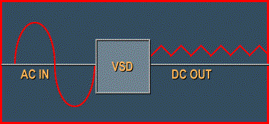
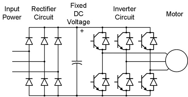
The VFD converts AC power from an incoming power supply to DC voltage. The VFD may also include a control mechanism by which to remotely communicate to the motor and driven load.
This control mechanism facilitates the connection of electronic equipment to monitor load speed, start and stop the motor, and perform various other functions to meet process requirements more effectively.
There are three different VFD design types presently on the market. In theory, these VFDs differ primarily in the type of rectification by which they convert AC power to DC power.
The most common centrifugal load applications that use VFDs are pumps, fans, and compressors. The most common constant torque load applications using VFDs are positive displacement pumps, gear pumps, reciprocating pumps, conveyors, extruders, extruder knife-cutters, mixers, and reciprocating compressors.
The primary considerations when selecting a VFD are:
I. Voltage Source Inverter (VSI) Variable Frequency Drive
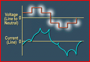
The VSI, or variable source inverter, was the earliest solid state VFD. It is sometimes called a "six-step" drive because of the voltage sent to the motor.
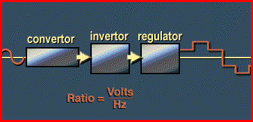
Variable source inverter operation is relatively simple. Basically, AC input voltage and frequency is converted to DC by rectifiers, then converted back to AC through the inverter section, which produces the desired voltage and frequency to meet the volts per hertz ratio at the VFD output.
The advantages of VSIs include good speed range, multiple motor control from a single unit, and simple regulator design.
Some disadvantages include:
II. Current Source Inverter (CSI) Variable Frequency Drive
Current Source Inverter, also called current-fed inverters, behave like a constant current generator, producing an almost square-wave of current. Current-source inverters are used instead of variable source inverters for large VFDs about 200 horsepower because of their simplicity, regeneration capabilities, reliability and lower cost.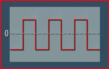
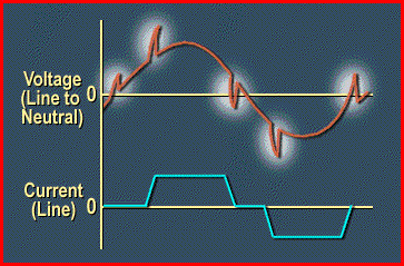
Although more rugged and reliable than VSIs, CSIs, have a poor power factor at low speeds, and are not suitable for multi-motor operation. Another disadvantage of CSIs is "cogging," jerky start/stop motions or pulsing shafts while running. A close examination of the CSIs output voltage waveform shows how this occurs.
III. Pulse Width Modulation (PWM) Variable Frequency Drive
The unique method by which this type VFD creates variable voltage gives the PWM VFD its name. Pulse width modulated, or PWM VFDs, deliver a constant voltage hertz ratio with no line notching and very stable current input for the motor.
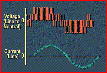
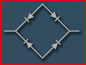 The pulse width modulation converter section uses a diode bridge to rectify AC power, rather than an SCR bridge. Since the input to the inverter section is constant, the inverter controls both voltage and frequency. Switching patterns of semiconductors function to convert DC power into AC output. These semiconductors might be transistors, GTOs, or SCRs.
Basically, the main advantages of using pulse width modulation over voltage or current inverters are high efficiency, constant power factor regardless of speed and no cogging problems. Other advantages include wide speed range, open circuit protection and multiple motor operation.
On the downside, PWM's require extra hardware for line regeneration capabilities, the equipment is more complex and some PWM units create significant audible noise.
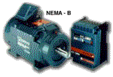
VFDs implement the most common motor in industry, the standard squirrel cage NEMA type B induction motor. The use of a standard motor means the VFD is suitable not only for new applications, but for retro-fitting older existing motors as well. All types of AC speed controls have in common this compatibility with standard motors.
In several aspects, VFDs stand in strong contrast to other variable speed controls. The main reasons that VFDs are more desirable than the other types of variable speed controls are: energy savings, improved process control, lower system maintenance, bypass capability, and multi-motor control.
1. Energy Savings
VFDs are by far the most efficient type of speed control, especially when used with centrifugal pumps and fans. When applying a VFD to a centrifugal pump or fan, load characteristics are governed by the "Laws of Affinity." These laws state that speed is proportional to current flow. Torque is proportional to the square of the speed change, and horsepower is proportional to the cube of the speed change.
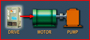
When plotting the horsepower curves, it can be seen that as the speed is reduced, the horsepower required at a given speed falls off very rapidly. The horsepower requirement for other types of speed control will also be reduced at reduced speeds, but not as much as the VFD.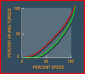 The difference in the horsepower requirements at a given speed between the VFD and any other type of variable speed control is that VFDs afford greater energy savings. This is one of the basics advantage of the VFD.
An inherent characteristic of an AC VFD is that it acts like a reduced voltage starter. That is, it will limit the amount of in-rush current. A motor started across the line will pull approximately 600% in-rush current. VFDs limit inrush current to a maximum of 150%. Power companies charge for supplying this in-rush current when starting a motor. This is called a demand charge. Limiting the amount of inrush current on large motors saves money through reducing the demand charge.
2. Improved Process Control
One goal of most plants is to automate their processes. The essential aspect of automation is better communication among plant instrumentation devices. The AC VFD is a solid state device, which lends itself nicely to process control networking. These VFDs receive process control signal inputs for start/stop, speed control, and output signals. The signals are then transmitted to a DCS system, PLC system, or back to personal computers. Other types of variable speed control are generally limited in, if not completely devoid of, these interface capabilities.
3. Bypass Capability
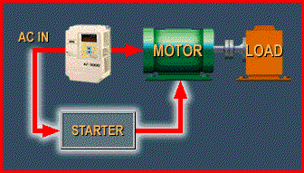
The VFD is very easily bypassed when critical applications require a means of back-up control. The VFD bypass, a starter in parallel with the VFD, allows bypass mode to ensue within seconds. Other types of variable speed control are physically coupled with the motor and the load. Whenever a speed control device fails, it must be uncoupled, repaired, and then re-installed. VFDs are bypassed in a matter of seconds whereas other types of speed control, along with their applications, may be down for hours or even weeks.
4. Multi-Motor Control
In theory, a single VFD has the capability to control multiple motors. Other types of variable speed control do not afford this possibility. The smaller physical size and lower initial cost of a VFD system are additional advantages.
5. Lower System Maintenance
The use of VFDs significantly reduces overall system maintenance. This applies especially to systems of mechanical design, such as eddy current clutch and variable pitch sheaf applications. VFDs help to reduce wear on belts, sheaves, gearboxes, and couplings. All of these ordinarily pose significant maintenance problems, due to wear caused by very caustic or otherwise harsh materials.
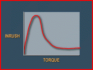
VFDs do not cycle motors on and off, as is common in other processes. This VFD simply slows the motor and load in order to operate in strict accordance with specifications. By eliminating the cycling process, VFDs function to eradicate troublesome inrush and torque pulsation otherwise present throughout entire operating systems.
1. Initial Cost
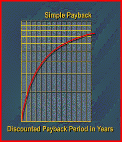
The initial cost of the VFD is generally greater than that of other variable speed controls. Initial cost is, in fact, often the primary obstacle for process plants wishing to install a VFD. However, the basic energy savings payback time and process control enhancement with these VFDs more than justifies the investment. There is an exception; pay-back is generally not significant if the average throttled speed requirement of a given application is low, between 90%-100%. As a general rule, a 2 1/2-year projected maximum pay-back interval sanctions the purchase of a VFD.
2. Maintenance Skill Set
Objections to the purchase of solid state design equipment generally come from maintenance personnel.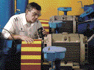 Mechanical devices obviously pose no problems, diagnostic or otherwise, for seasoned maintenance workers. A cursory inspection is enough to see whether and why devices fail. VFDs, like any solid state device, require special troubleshooting practical and theory knowledge. VFDs have significantly improved in their diagnostic capabilities. This entails additional and often perennial training for maintenance personnel unfamiliar with solid state design technology.
3. Low Speed Overheating
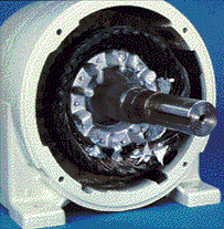 With constant torque applications, there is a possibility that the motor will overheat during low speed operation. A constant torque load draws the same amount of current regardless of the motor's operating speed. This creates a problem at very low speeds, because the VFD reduces motor frequency in order to decrease motor speed. If the motor produces a high level of heat while operating at low speed, overheating results.
As a rule of thumb, a fully loaded motor with Class B insulation running at 50% rated speed on a constant torque load will not overheat. If the motor is run below 50% speed continuously, it will overheat. Basically, the speed of a fully loaded motor with Class F insulation may be decreased to approximately 20% speed without overheating. The lower the continuous operating speed below the motor overheating point, the more the motor and VFD must be derated.
4. Output Harmonics
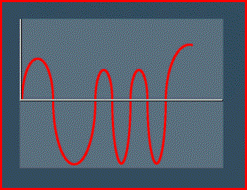
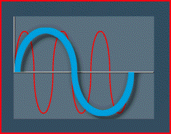
The output wave form generated by the VFD is a non-linear wave-form. This wave-form creates harmonics in the motor. The harmonics are multiples of a fundamental frequency with a current component. The current component will create heat in the motor. As a rule of thumb, VFDs create between 5 to 8% more heating in a motor when compared to that same motor running on a sinusoidal waveform from the power line. The way to overcome this problem is to use a Class F insulation, inverter rated motor.
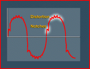 5. Induced Harmonics - Distortion and Line-Notching
The VFD is a non-linear load, which induces harmonics to the power source line. Two aspects of harmonics are distortion and line-notching. Distortion is a result of the non-sinusoidal waveform the VFD generates. This acts to pull the current off of the power line in the form of non-sinusoidal pulses.
The line notching is caused by VFDs with an SCR rectifier. When the SCR's continuously fire at a particular point on the AC waveform, the harmonics will include notching back to the power line.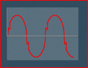 These can severely distort the power line and if not properly protected, can hinder the operation of other devices on your power line.
All VFDs that have SCR rectifiers, both AC and DC, should include either an isolation transformer, or line reactors on the input of the VFD, to protect the power source from excessive distortion.
(this paper include VFD types, advantages of VFDs and disadvantages basics as a tutorial)
VFD's function to adjust motor speed to better fulfill the requirements of a driven load. The results are better process control and reduced energy consumption. VFD systems are fairly expensive, but provide an excellent degree of control over plant operations. In most cases, the reduction of energy costs following the installation of a VFD is enough to offset, if not completely pay for, high initial costs.

The VFD converts AC power from an incoming power supply to DC voltage. The VFD may also include a control mechanism by which to remotely communicate to the motor and driven load.

This control mechanism facilitates the connection of electronic equipment to monitor load speed, start and stop the motor, and perform various other functions to meet process requirements more effectively.
Variable Frequency Drive types
There are three different VFD design types presently on the market. In theory, these VFDs differ primarily in the type of rectification by which they convert AC power to DC power.
The most common centrifugal load applications that use VFDs are pumps, fans, and compressors. The most common constant torque load applications using VFDs are positive displacement pumps, gear pumps, reciprocating pumps, conveyors, extruders, extruder knife-cutters, mixers, and reciprocating compressors.
The primary considerations when selecting a VFD are:
-
the nature of the application,
-
cost, and
- the operating environment.
I. Voltage Source Inverter (VSI) Variable Frequency Drive
The VSI, or variable source inverter, was the earliest solid state VFD. It is sometimes called a "six-step" drive because of the voltage sent to the motor.

Variable source inverter operation is relatively simple. Basically, AC input voltage and frequency is converted to DC by rectifiers, then converted back to AC through the inverter section, which produces the desired voltage and frequency to meet the volts per hertz ratio at the VFD output.
The advantages of VSIs include good speed range, multiple motor control from a single unit, and simple regulator design.
Some disadvantages include:
- decreasing power factor with decreasing speed,
- induced harmonics, and
- "cogging," jerky start/stop motions.

II. Current Source Inverter (CSI) Variable Frequency Drive
Current Source Inverter, also called current-fed inverters, behave like a constant current generator, producing an almost square-wave of current. Current-source inverters are used instead of variable source inverters for large VFDs about 200 horsepower because of their simplicity, regeneration capabilities, reliability and lower cost.

Although more rugged and reliable than VSIs, CSIs, have a poor power factor at low speeds, and are not suitable for multi-motor operation. Another disadvantage of CSIs is "cogging," jerky start/stop motions or pulsing shafts while running. A close examination of the CSIs output voltage waveform shows how this occurs.

III. Pulse Width Modulation (PWM) Variable Frequency Drive
The unique method by which this type VFD creates variable voltage gives the PWM VFD its name. Pulse width modulated, or PWM VFDs, deliver a constant voltage hertz ratio with no line notching and very stable current input for the motor.
 The pulse width modulation converter section uses a diode bridge to rectify AC power, rather than an SCR bridge. Since the input to the inverter section is constant, the inverter controls both voltage and frequency. Switching patterns of semiconductors function to convert DC power into AC output. These semiconductors might be transistors, GTOs, or SCRs.
Basically, the main advantages of using pulse width modulation over voltage or current inverters are high efficiency, constant power factor regardless of speed and no cogging problems.
 Other advantages include wide speed range, open circuit protection and multiple motor operation.
On the downside, PWM's require extra hardware for line regeneration capabilities, the equipment is more complex and some PWM units create significant audible noise.
Variable Frequency Drive Advantages

VFDs implement the most common motor in industry, the standard squirrel cage NEMA type B induction motor. The use of a standard motor means the VFD is suitable not only for new applications, but for retro-fitting older existing motors as well. All types of AC speed controls have in common this compatibility with standard motors.
In several aspects, VFDs stand in strong contrast to other variable speed controls. The main reasons that VFDs are more desirable than the other types of variable speed controls are: energy savings, improved process control, lower system maintenance, bypass capability, and multi-motor control.
1. Energy Savings
VFDs are by far the most efficient type of speed control, especially when used with centrifugal pumps and fans. When applying a VFD to a centrifugal pump or fan, load characteristics are governed by the "Laws of Affinity." These laws state that speed is proportional to current flow. Torque is proportional to the square of the speed change, and horsepower is proportional to the cube of the speed change.

When plotting the horsepower curves, it can be seen that as the speed is reduced, the horsepower required at a given speed falls off very rapidly. The horsepower requirement for other types of speed control will also be reduced at reduced speeds, but not as much as the VFD.
 The difference in the horsepower requirements at a given speed between the VFD and any other type of variable speed control is that VFDs afford greater energy savings. This is one of the basics advantage of the VFD.
An inherent characteristic of an AC VFD is that it acts like a reduced voltage starter. That is, it will limit the amount of in-rush current. A motor started across the line will pull approximately 600% in-rush current. VFDs limit inrush current to a maximum of 150%. Power companies charge for supplying this in-rush current when starting a motor. This is called a demand charge. Limiting the amount of inrush current on large motors saves money through reducing the demand charge.
2. Improved Process Control
One goal of most plants is to automate their processes. The essential aspect of automation is better communication among plant instrumentation devices. The AC VFD is a solid state device, which lends itself nicely to process control networking. These VFDs receive process control signal inputs for start/stop, speed control, and output signals. The signals are then transmitted to a DCS system, PLC system, or back to personal computers. Other types of variable speed control are generally limited in, if not completely devoid of, these interface capabilities.
3. Bypass Capability
The VFD is very easily bypassed when critical applications require a means of back-up control. The VFD bypass, a starter in parallel with the VFD, allows bypass mode to ensue within seconds. Other types of variable speed control are physically coupled with the motor and the load. Whenever a speed control device fails, it must be uncoupled, repaired, and then re-installed. VFDs are bypassed in a matter of seconds whereas other types of speed control, along with their applications, may be down for hours or even weeks.

4. Multi-Motor Control
In theory, a single VFD has the capability to control multiple motors. Other types of variable speed control do not afford this possibility. The smaller physical size and lower initial cost of a VFD system are additional advantages.
5. Lower System Maintenance
The use of VFDs significantly reduces overall system maintenance. This applies especially to systems of mechanical design, such as eddy current clutch and variable pitch sheaf applications. VFDs help to reduce wear on belts, sheaves, gearboxes, and couplings. All of these ordinarily pose significant maintenance problems, due to wear caused by very caustic or otherwise harsh materials.

VFDs do not cycle motors on and off, as is common in other processes. This VFD simply slows the motor and load in order to operate in strict accordance with specifications. By eliminating the cycling process, VFDs function to eradicate troublesome inrush and torque pulsation otherwise present throughout entire operating systems.
Variable Frequency Drive Disadvantages
1. Initial Cost
The initial cost of the VFD is generally greater than that of other variable speed controls. Initial cost is, in fact, often the primary obstacle for process plants wishing to install a VFD. However, the basic energy savings payback time and process control enhancement with these VFDs more than justifies the investment. There is an exception; pay-back is generally not significant if the average throttled speed requirement of a given application is low, between 90%-100%. As a general rule, a 2 1/2-year projected maximum pay-back interval sanctions the purchase of a VFD.

2. Maintenance Skill Set
Objections to the purchase of solid state design equipment generally come from maintenance personnel.
 Mechanical devices obviously pose no problems, diagnostic or otherwise, for seasoned maintenance workers. A cursory inspection is enough to see whether and why devices fail. VFDs, like any solid state device, require special troubleshooting practical and theory knowledge. VFDs have significantly improved in their diagnostic capabilities. This entails additional and often perennial training for maintenance personnel unfamiliar with solid state design technology.
3. Low Speed Overheating
 With constant torque applications, there is a possibility that the motor will overheat during low speed operation. A constant torque load draws the same amount of current regardless of the motor's operating speed. This creates a problem at very low speeds, because the VFD reduces motor frequency in order to decrease motor speed. If the motor produces a high level of heat while operating at low speed, overheating results.
As a rule of thumb, a fully loaded motor with Class B insulation running at 50% rated speed on a constant torque load will not overheat. If the motor is run below 50% speed continuously, it will overheat. Basically, the speed of a fully loaded motor with Class F insulation may be decreased to approximately 20% speed without overheating. The lower the continuous operating speed below the motor overheating point, the more the motor and VFD must be derated.
4. Output Harmonics


The output wave form generated by the VFD is a non-linear wave-form. This wave-form creates harmonics in the motor. The harmonics are multiples of a fundamental frequency with a current component. The current component will create heat in the motor. As a rule of thumb, VFDs create between 5 to 8% more heating in a motor when compared to that same motor running on a sinusoidal waveform from the power line. The way to overcome this problem is to use a Class F insulation, inverter rated motor.
 5. Induced Harmonics - Distortion and Line-Notching
 The VFD is a non-linear load, which induces harmonics to the power source line. Two aspects of harmonics are distortion and line-notching. Distortion is a result of the non-sinusoidal waveform the VFD generates. This acts to pull the current off of the power line in the form of non-sinusoidal pulses.
The line notching is caused by VFDs with an SCR rectifier. When the SCR's continuously fire at a particular point on the AC waveform, the harmonics will include notching back to the power line.
 These can severely distort the power line and if not properly protected, can hinder the operation of other devices on your power line.
All VFDs that have SCR rectifiers, both AC and DC, should include either an isolation transformer, or line reactors on the input of the VFD, to protect the power source from excessive distortion.
Post a Comment:
You may also like:
Featured Articles
What is VFD, How it works? - VFD ...
 VFD is shorted for Variable Frequency Drive (also known as AC Drives and Inverters) -- that's used to make an AC motor working in ...
 VFD is shorted for Variable Frequency Drive (also known as AC Drives and Inverters) -- that's used to make an AC motor working in ...
VFD: Insulated Gate Bipolar Transistor ...
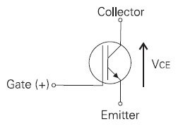 IGBT (insulated gate bipolar transistor) provides a high switching speed necessary for PWM VFD operation. IGBTs are capable of ...
 IGBT (insulated gate bipolar transistor) provides a high switching speed necessary for PWM VFD operation. IGBTs are capable of ...
Three phase inverters
 In the variable frequency drive rectifier paper, it explains how to go from three phase alternating current voltage to a direct ...
 In the variable frequency drive rectifier paper, it explains how to go from three phase alternating current voltage to a direct ...
Variable Frequency Drive Harmonics and ...
A discussion of the benefits of variable frequency drives often leads to a question regarding electrical harmonic distortion ...
Variable frequency drive Energy saving
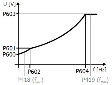 Energy can be saved in a VFD by reducing the losses in the electric motor or by reducing the energy consumption of the variable ...
 Energy can be saved in a VFD by reducing the losses in the electric motor or by reducing the energy consumption of the variable ...
VFD manufacturers

http://www.vfds.org/image/09055853164.gif