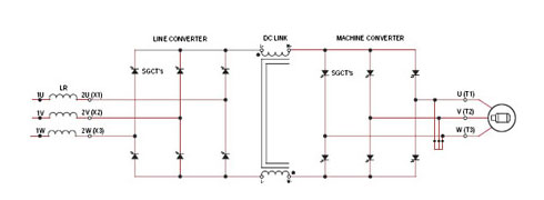
A bypass contactor is intended for use in case of a VFD failure for short-time emergency service. A typical diagram of the power circuit connection of a variable frequency drive bypass contactor is shown in the figure. The isolation contactor electrically isolates the VFD during bypass operation & is mechanically & electrically interlocked with the bypass contactor to ensure that both cannot be closed at the same time. Upon a sensed malfunction of the variable frequency drive, the control circuit automatically opens the VFD isolation contactor & closes the bypass contactor to keep the motor connected to the source.
Electromagnetic interference (EMI), also called electrical noise, is the unwanted signals generated by electrical & electronic equipment. EMI VFD problems range from corrupted data transmission to electric motor drive damage. Modern VFDs using IGBT switches for motor frequency control are very efficient because of their high switching speed. Unfortunately the high-speed switching also results in much higher EMI being generated. All VFD manufacturers detail installation procedures that must be followed in order to prevent excessive noise on both sides of the VFD.
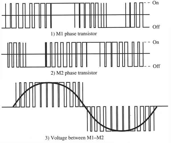
The diagram below shows a common waveform for a pulse-width modulation (PWM) circuit in the VFD. The transistors in the PWM circuit are switched on & off approximately 12 times each half-cycle. The on & off cycles create the overall frequency waveform for the output signal. The output waveform of the PWM section looks like a traditional three-phase signal to the motor. If one places an isolated-case oscilloscope across any two of the output leads of the VFD, one will see a signal that looks similar to the one in the diagram.


To evaluate benefits of installing a VFD, a detailed load analysis is required. This means we have to calculate the horsepower requirements for each level of operation.
Because we are dealing with a pumping application, we must obey the affinity laws for fans and pumps. Part of this law states that horsepower varies as the cube of the fan or pump speed variance.

Power requirements at 75% flow would require 100 horsepower times 75% cubed,or 42.2 horsepower. At 50% flow the motor would only need to develop 12.5horsepower. At 100% flow, the motor will still develop 100% power, or 100 horsepower.
It is this difference in required horsepower that will make the economic difference if we add the variable frequency drive. The question then becomes, how much will it save?
Because we are dealing with a pumping application, we must obey the affinity laws for fans and pumps. Part of this law states that horsepower varies as the cube of the fan or pump speed variance.

Power requirements at 75% flow would require 100 horsepower times 75% cubed,or 42.2 horsepower. At 50% flow the motor would only need to develop 12.5horsepower. At 100% flow, the motor will still develop 100% power, or 100 horsepower.
It is this difference in required horsepower that will make the economic difference if we add the variable frequency drive. The question then becomes, how much will it save?
The filter section of the VFD uses capacitors & an inductor to filter the voltage & current. The capacitors have a pre-charge circuit that allows the capacitors to reach full charge slowly so that they are not damaged. The capacitors are connected in parallel with the DC bus, & the inductor is connected in series with the negative DC bus wire. A set of resistors is provided to discharge the capacitors anytime power is removed. You should always allow sufficient time for the capacitors to discharge before you try to work on the solid-state components in the VFD. The filter allows the pulsing DC voltage to be changed to pure DC.
The output section of the VFD converts the DC voltage back to three-phase voltage. This section uses pulse-width modulation (PWM) techniques to switches three pairs of transistors on & off up to 12 times during each half-wave to produce a three phase output. The amplitude of the signal determines the amount of voltage for the AC voltage, & the frequency of the signal will determine the frequency of the output of the VFD. In most cases the output frequency can be any value between 0-120 Hz. Some VFDs allow the upper frequency to reach 400 Hz.
The output transistors are connected across the DC bus. One transistor is connected to the positive DC bus wire, & when it's switched on & off, it will provide the positive half-cycle for one phase of the AC signal. The second transistor is connected to the negative DC bus wire, & when it's switched on & off, it will provide the negative half-cycle for one phase of the AC signal. The base VFD board provides the PWM signals for all of the transistors. The VFD contains a microprocessor that accepts the command signal & determines the correct frequency & voltage for the output transistors.
The two most important emerging technologies associated with motor control are variable frequency drives & programmable logic controllers. VFDs allow motor driven loads to operate within a wide range of speeds. Con trolling motor speeds to load requirements can increase both the efficiency & performance of a motor installation. A programmable logic controller (PLC) is a type of computer commonly used in motor control applications. The traditional motor control circuit is hard-wired while PLC control is program-based. This section deals with the unique installation requirements of these electronic control systems.
The primary function of any electronic VFD is to control the speed, torque, acceleration, deceleration, & direction of rotation of a machine. Unlike constant speed systems, the VFD permits the selection of an infinite number of speeds within its operating range.
The primary function of any electronic VFD is to control the speed, torque, acceleration, deceleration, & direction of rotation of a machine. Unlike constant speed systems, the VFD permits the selection of an infinite number of speeds within its operating range.
Flux vector control improves on the basic V/Hz control technique by providing both a magnitude & angle between the voltage & current. Volts per hertz variable frequency drives control only the magnitude. Vector VFDs come in two types, open loop & closed loop , based on the way they get their feedback information. Open loop is actually a misnomer because it’s actually a closed loop sys tem, but the feedback loop comes from within the variable frequency drive itself instead of an external encoder. For this reason there is a trend to refer to open-loop VFDs as sensor less vector VFDs. Sensorless vector control removes a major source of complexity & simplifies the variable frequency drive installation.
The block diagram of a sensorless flux vector control VFD is shown as:

The block diagram of a sensorless flux vector control VFD is shown as:

The VFD in the diagram below has two types of on/off outputs available -- they are shown on the right side of the diagram. A set of NO (normally open) contacts is provided at terminals TB2-9 and TB2-10. These contacts are controlled by the VFD and their function can be selected in the VFD parameters. For example, these contacts can be selected to close when the VFD is enabled, or they can be used to indicate the VFD in a fault condition. A solid-state output is available at terminals TB2-19 and TB2-20. This circuit is basically the emitter and collector of a transistor. When the VFD controls this circuit, it sends a signal to the transistor base, which in turn causes the collector-emitter circuit to go to saturation.
The VFD control terminals can be configured, on an individual terminal basis, to suit a wide variety of applications. This provides enormous flexibly.
The factory default terminal configuration provides for single direction control from either the terminal strip or the front panel console, as selected by a local / remote input on the terminal strip. There is a menu function to restore the terminal configuration and all VFD parameters to the factory default state should you wish to do so.
The factory default terminal configuration provides for single direction control from either the terminal strip or the front panel console, as selected by a local / remote input on the terminal strip. There is a menu function to restore the terminal configuration and all VFD parameters to the factory default state should you wish to do so.
Practical resolution of interference issues usually centres around conducted rather than radiated issues and especially paying close attention to the path of high frequency common mode currents around the installation. In many instances, the use of screened VFD cables will be of assistance.
In order to achieve the required electrical performance at high frequencies, it is essential that the screen of the VFD cable have a 360º connection to both the gland plate of the metallic (typically switchboard) enclosure containing the VFD and the motor terminal box. The correct type of metal cable gland to suit the screened cable should be used. The protective earth (PE) conductor should be terminated in the usual way to meet the local wiring codes.
In order to achieve the required electrical performance at high frequencies, it is essential that the screen of the VFD cable have a 360º connection to both the gland plate of the metallic (typically switchboard) enclosure containing the VFD and the motor terminal box. The correct type of metal cable gland to suit the screened cable should be used. The protective earth (PE) conductor should be terminated in the usual way to meet the local wiring codes.
Variable frequency drive power cables between the various system components are the responsibility of the installer and the size and type to be used should be selected to suit the application and on the basis of the continuous current rating of the variable frequency drive and a minimum temperature rating of 70C.
VFD cables sizes should be selected according to local wiring rules using the currents given from the VFD manufacturers. Note that the power terminals of the VFD enclosure and the input/output line reactors are intended for use with cables terminated in crimp lugs with a single hole to match the diameter of the hole or bolt provided.
VFD cables sizes should be selected according to local wiring rules using the currents given from the VFD manufacturers. Note that the power terminals of the VFD enclosure and the input/output line reactors are intended for use with cables terminated in crimp lugs with a single hole to match the diameter of the hole or bolt provided.
To calculate the value of a variable frequency drive retrofit for a customer, contractors in-the-know state that one must first evaluate the customer's energy consumption and price. For example, suppose the chiller is a 1,300-ton system with air handler and pumps. If you broke down motor horsepower (hp) within a typical large facility with an applied HVAC system, the chillers represent 55 percent of the hp in the system, air handlers around one-half of that, and pumps and cooling towers represent the balance of the hp.
General modeling parameters include the number of operating hours, the cost of the electricity, the efficiency of the motor, and operating hours by percent total load. In this example, 5,600 annual operating hours is used and a 6 cents per kWh electricity cost. The 1,300-ton system derived the following benefit by changing from constant speed to variable speed:
General modeling parameters include the number of operating hours, the cost of the electricity, the efficiency of the motor, and operating hours by percent total load. In this example, 5,600 annual operating hours is used and a 6 cents per kWh electricity cost. The 1,300-ton system derived the following benefit by changing from constant speed to variable speed:
- Annual energy cost, constant speed: $364,063.
- VFD operation: $197, 105
- Energy cost reduction/savings: $166,958
Featured Articles
Variable Frequency Drive Harmonics and ...
A discussion of the benefits of variable frequency drives often leads to a question regarding electrical harmonic distortion ...
Three phase inverters
 In the variable frequency drive rectifier paper, it explains how to go from three phase alternating current voltage to a direct ...
 In the variable frequency drive rectifier paper, it explains how to go from three phase alternating current voltage to a direct ...
Variable frequency drive Advantages & ...
VFDs are good for variable speed, in a water pump this is used to maintain a steady pressure, they will smooth out variances in ...
Variable frequency drive Rectifier
 To understand variable frequency drive (VFD) better, it's necessary to explain some of the main parts of the variable frequency ...
 To understand variable frequency drive (VFD) better, it's necessary to explain some of the main parts of the variable frequency ...
VFD controlled Induction motor ...
 This paper presents a procedure to measure the efficiency on an induction motor fed by a VFD by the all operation range to speed ...
 This paper presents a procedure to measure the efficiency on an induction motor fed by a VFD by the all operation range to speed ...
VFD manufacturers
