What's the difference between the current measured at the input vs. the output of the Variable Frequency Drive? Is it lower at the input compared to the output? Are common multimeters able to measure the correct output voltage and current?
The VFD uses a PWM output voltage waveform. Most multimeters will measure the peak voltage and calculate the average from that. In order to measure the voltage, a low-pass filter is required to remove the high-frequency component.
At frequencies below 60Hz, the output voltage from the VFD is below the line voltage. Since VIin = VIout (or Powerin = Powerout, Pin = Pout), the output current must be higher than the input current. That is, at half speed, the output voltage is half, so the output current is double.
Except for the losses in the VFD. at one-half speed, the output current is typically slightly less than twice the input current because the losses are greater in the circuit at that speed (perhaps 5% or even 10%?), but the input current will include those losses.
VFD is shorted for Variable Frequency Drive (also known as AC Drives and Inverters) -- that's used to make an AC motor working in variable speed (among other parameters). This is definition used in all topical discussion on this paper.
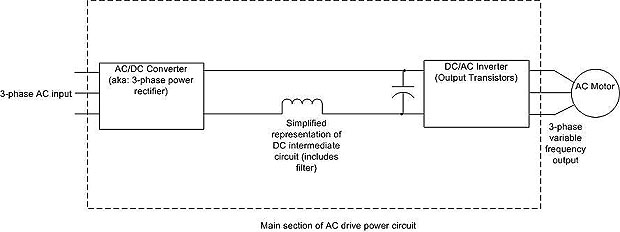
The block diagram below contains three separate sections to indicate the VFD basic working principle:

Above: The VFD shown as three separate sections: rectifier (where AC is converted to DC); the DC intermediate circuit which contains the capacitor and inductor for filtering. The third section is the DC-to-AC inverter where DC is turned back to three-phase AC.
The block diagram below contains three separate sections to indicate the VFD basic working principle:
- the rectifier
- the filter
- the switching section that uses regular transistors, darlington pair transistors, or insulated gate bipolar transistors (IGBT) to invert the DC voltage back to AC voltage with the proper frequency.

Above: The VFD shown as three separate sections: rectifier (where AC is converted to DC); the DC intermediate circuit which contains the capacitor and inductor for filtering. The third section is the DC-to-AC inverter where DC is turned back to three-phase AC.
The use of line reactors in variable frequency drive application is a complex issue. We have attempted to provide some general information in this summary, but more complete details are available in the IEEE standard and attachment links provided below.
Line reactors are sometimes used with variable frequency drive controls because they smooth out electrical power supply variations. They are used to correct a problem with the electrical supply system, not a problem with the specific VFD application. The technical evaluation of the power supply, and requirements for line reactors is defined in the ANSI / IEEE standard 519. In addition to using line reactors between the power supply and variable frequency drive, they may also be used on the outlet side (between the VFD and motor) with long wire runs (not addressed in this document).
Line reactors are sometimes used with variable frequency drive controls because they smooth out electrical power supply variations. They are used to correct a problem with the electrical supply system, not a problem with the specific VFD application. The technical evaluation of the power supply, and requirements for line reactors is defined in the ANSI / IEEE standard 519. In addition to using line reactors between the power supply and variable frequency drive, they may also be used on the outlet side (between the VFD and motor) with long wire runs (not addressed in this document).
An overcurrent protection device is required in the AC supply to the VFD. The purpose of this device is twofold:
- To provide thermal protection for the VFD cables etc between the location of the overcurrent protective device (usually at the origin of the relevant supply sub-circuit) and the VFD. This is predominantly a measure to prevent injury and property damage from melting and fire.
- To limit the energy available at the location of a short circuit or near short circuit in the unlikely, but possible, event of a major arcing fault in wiring or within the VFD enclosure. This measure is to control the risk of personal injury and property damage due to arc flash, conductor erosion, explosion and the like.
- The variable frequency drive must be mounted on a vibration free vertical surface, away from heat radiating sources. Do not mount the variable frequency drive in direct sunlight or on a hot surface.
- The variable frequency drive must be mounted vertically. No other mounting orientation is acceptable.
- If the VFD is mounted inside another enclosure, the total heat dissipation and resulting temperature rise in the enclosure must be allowed for.
- Attention is drawn to the potential for condensation in vulnerable environments. Additional precautions may be required for all enclosure types.
- The installation location and environment should provide for safe access and working conditions for service personnel. Do not mount the variable frequency drive in "confined spaces"
- Do not drill holes in the enclosure except in the gland plate.
- Remove the gland plate before drilling cable holes.
- Do not allow metal shavings or any other conductive material to enter the enclosure or damage may result.
This paper is intended to be a guide for the installation of VFDs to ensure adequate cooling or ventilation is provided. All power electronic equipment will dissipate heat which must be removed to prevent overheating of the semiconductor devices or other components. The installation and environmental factors must be considered with all external sources of heat removed or minimized. An important consideration is the effects of direct sunlight, in which all precautions should be taken to remove the effects by providing adequate shelter.
The scope of this technical note is to provide guidance to calculate ventilation / cooling requirements of variable frequency drives, but the calculations make no consideration for external factors such as direct sunlight, other heat sources etc.
The scope of this technical note is to provide guidance to calculate ventilation / cooling requirements of variable frequency drives, but the calculations make no consideration for external factors such as direct sunlight, other heat sources etc.
 The VFD contains high energy circuits that may be hazardous. Do not operate the VFD with the door open or any part of the enclosure removed. Do not touch the terminals of the VFD or any associated motor and wiring when it is energised, even if the VFD and motor are stopped. Electric shock may result. Do not modify this equipment electrically, mechanically or otherwise. Modification may create safety hazards.
Think of a VFD driving an induction motor. Strictly speaking, as the variable frequency drive does not cause any significant displacement of the voltage and current waveforms on its input it could be thought to have a displacement power factor of close to unity.
All very nice, and depending on the type of metering it may even appear as unity Power Factor, but given the distortion present on the input to the VFD to the rectifiers in circuit the correct representation of the Power Factor should be the Apparent Power Factor. So should we now correct the building Power Factor using Harmonic Filtering or by conventional power factor correction capacitors?
All very nice, and depending on the type of metering it may even appear as unity Power Factor, but given the distortion present on the input to the VFD to the rectifiers in circuit the correct representation of the Power Factor should be the Apparent Power Factor. So should we now correct the building Power Factor using Harmonic Filtering or by conventional power factor correction capacitors?
Generally when it comes to VFDs, industry practice is to use a low level of IP rating for equipment which will be mounted within another enclosure such as a clean and dry switchboard.
When it comes to stand alone wall mounted equipment consideration should be given to the mounting environment. Is it clean, will it be subject to water spray such as from fire sprinklers, will it be mounted in a corrosive environment such as could be found close to cooling towers, will it be subject to airborne salt contamination such as beachside or harbour side locations, will it be mounted in proximity to pressurised pipework or pumps, where there is the possibility of pipe or seal failures which may spray water over the variable frequency drive, and most importantly is the variable frequency drive being used as part of a mission critical application or as part of fire safety or life saving system? Give these aspects careful consideration, some would be worthy of a Stainless Steel enclosure solution.
As well as looking after our own designed and manufactured VFDs, our service department is frequently asked to service other brands of equipment. Our records clearly show that whether it is equipment or other VFD brands the longevity and reliability of electronic equipment is very highly correlated to the level of protection against ingress of dust and water and that IP66 protected equipment delivers far superior results for equipment life and reliability when compared to lower levels of protection. Be aware that variable frequency drive's pack a lot of circuitry into tiny spaces and the voltages are high so the last thing you want is dust entering the electronics enclosure with the potential to cause damaging short circuits. Think high levels of atmospheric humidity and overnight condensation, far better to keep moisture out.
When you install a VFD on an electric motor that is driving critical equipment in your factory, building or farm etc you need to be confident that that equipment will perform regardless of the environment that it is installed in.
Critical to getting that level of performance from your VFD is making sure that the enclosure that has been used for your VFD is capable of protecting the vital components of the VFD from dust, dirt, particles, water and other liquids.
Critical to getting that level of performance from your VFD is making sure that the enclosure that has been used for your VFD is capable of protecting the vital components of the VFD from dust, dirt, particles, water and other liquids.
Tags: VFD installation
Like most things in life there is more than one way to carry out a variable frequency drive bypass procedure.
Having considered the above and concluded that the electrical supply, circuit breaker or fuses and any other electrical components are adequate for the resultant bypass starting current, that no damage will result to pipe work, seals, ducting, dampers etc, and that removal of the VFD from the controls circuit will not impede the continued satisfactory operation of the controls and most importantly that the bypass operation will achieve the desired result, then you are ready to proceed with the bypass.
The easiest and least complicated way would be to simply have your electrician remove the input and output power cables and connect then in a safe manner external to the VFD. If the VFD is to be removed then all controls connections should also be disconnected. The downside to this is you need a suitably experienced licensed electrician to be available in a timely manner and to have previously determined the suitability of this arrangement to meet your needs.
When we are assisting with selection of our Variable Frequency Drives we look at your application, is it being used for Constant or Variable Torque (Standard Pumps are considered a Variable Torque), the Full load current of the motor, Supply voltages, ambient temperatures, ETC. The VFDs are rated and sized by Amperage and it will come down to making sure it is not undersized, Talking with your suppliers engineers are the safest way to make sure you get the best value for your money without getting problems from being undersized.
Featured Articles
Variable Frequency Drive Harmonics and ...
A discussion of the benefits of variable frequency drives often leads to a question regarding electrical harmonic distortion ...
Three phase inverters
 In the variable frequency drive rectifier paper, it explains how to go from three phase alternating current voltage to a direct ...
 In the variable frequency drive rectifier paper, it explains how to go from three phase alternating current voltage to a direct ...
Variable frequency drive Advantages & ...
VFDs are good for variable speed, in a water pump this is used to maintain a steady pressure, they will smooth out variances in ...
Variable frequency drive Rectifier
 To understand variable frequency drive (VFD) better, it's necessary to explain some of the main parts of the variable frequency ...
 To understand variable frequency drive (VFD) better, it's necessary to explain some of the main parts of the variable frequency ...
VFD controlled Induction motor ...
 This paper presents a procedure to measure the efficiency on an induction motor fed by a VFD by the all operation range to speed ...
 This paper presents a procedure to measure the efficiency on an induction motor fed by a VFD by the all operation range to speed ...
VFD manufacturers
